Waveguide Flanges
Complete reference library for rectangular waveguide flange types. Technical drawings, dimensional specifications, MIL-DTL-3922 part numbers, compatibility charts, and selection guidelines for microwave and millimeter-wave systems.
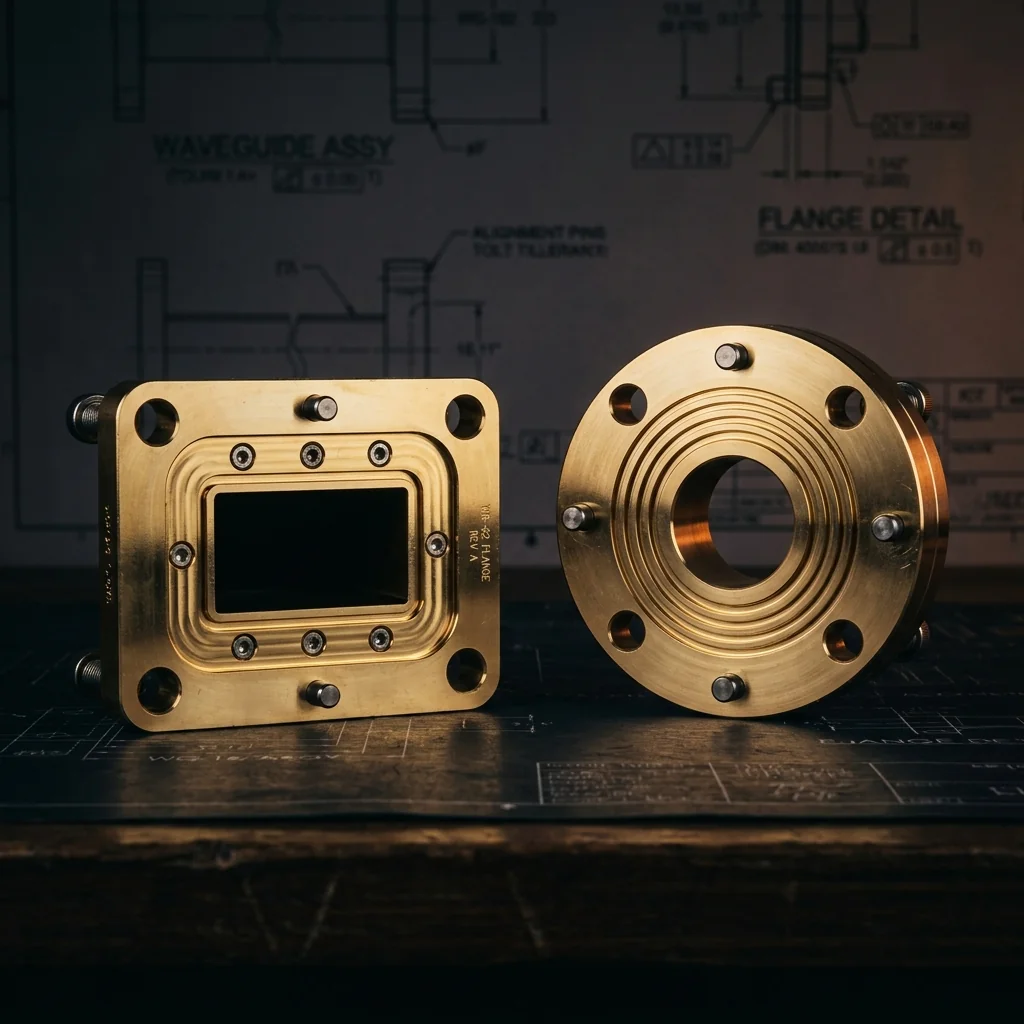
Flange Types at a Glance
Waveguide flanges provide the mechanical and RF interface between waveguide sections. Each type serves a specific purpose in the system architecture.
Flange Specification Pages
Each page includes technical drawings, dimensional tables, MIL-spec part numbers, tolerances, and application guidance. Select a flange type below.
Finished round contact flange dimensions per MIL-DTL-3922/67. Front view and cross-section drawings with all critical dimensions. Covers UG-425, UG-381, UG-383, UG-385, and UG-387 from WR-42 through WR-3.
View Specifications → LiveUn-bored flange blank dimensions per MIL-DTL-3922/67. Pilot bore specifications, bolt patterns, and tolerances. Available with or without alignment pin holes. K-band through J-band.
View Specifications → LiveChoke flange dimensions per MIL-DTL-3922/59 and /71. Quarter-wave groove specifications, groove depth and diameter, choke joint geometry, and mating requirements for S-band through W-band.
View Specifications → LiveFinished square cover flange dimensions per MIL-DTL-3922/1. Waveguide aperture, bolt patterns, alignment pins, and body dimensions for WR-284 through WR-42. Includes 11 sizes with choke flange cross-reference.
View Specifications → LiveO-ring groove dimensions, seal material guide, and pressure ratings for gasket cover flanges. Square and round contact configurations with AS568 O-ring sizing for gas-filled waveguide systems.
View Specifications →Flange Mating Compatibility
Not all flange combinations provide optimal RF performance. The table below shows which flange type pairs are recommended, acceptable, or not recommended.
| Cover | Choke | Square Cover | Square Choke | |
|---|---|---|---|---|
| Cover | OK | Preferred | N/A | N/A |
| Choke | Preferred | Avoid | N/A | N/A |
| Square Cover | N/A | N/A | OK | Preferred |
| Square Choke | N/A | N/A | Preferred | Avoid |
Preferred: Cover + Choke provides the best RF performance. The choke joint compensates for minor surface imperfections and reduces sensitivity to bolt torque variations.
OK: Two cover flanges work well when surfaces are flat, clean, and properly torqued. Slightly more sensitive to alignment and surface condition than Cover + Choke.
Avoid: Two choke flanges create a double choke cavity that can resonate at certain frequencies, causing high insertion loss at unpredictable frequencies within the band.
Waveguide Flange Engineering Guide
What Is a Waveguide Flange?
A waveguide flange is a precisely machined metallic interface that provides both the mechanical attachment and the RF connection between two waveguide sections or between a waveguide and a component (such as an antenna feed, filter, coupler, or test port). The flange must maintain precise alignment of the waveguide apertures while providing low insertion loss and minimal RF leakage at the joint.
The UG Designation System
The UG (United Government) designation system assigns unique interface numbers to specific flange configurations. Each UG number identifies the flange type (cover or choke), the waveguide size, and the physical dimensions of the flange body. This system ensures interchangeability between manufacturers worldwide.
- UG-425/U: Round contact cover flange for WR-42 (K-band, 18-26.5 GHz)
- UG-381/U: Round contact cover flange for WR-28 (Ka-band, 26.5-40 GHz)
- UG-383/U: Round contact cover flange for WR-22 (Q-band, 33-50 GHz)
- UG-385/U: Round contact cover flange for WR-15 (V-band, 50-75 GHz)
- UG-387/U: Round contact cover flange for WR-12 through WR-3 (E through J-band)
- UG-135/U: Square cover flange for WR-90 (X-band, 8.2-12.4 GHz)
- UG-136/U: Square choke flange for WR-90 (X-band)
MIL-DTL-3922 Specification
MIL-DTL-3922 (formerly MIL-F-3922) is the governing military specification for waveguide flanges. It defines dimensional tolerances, material requirements, plating specifications, and acceptance testing procedures. Key slash sheets include:
- /1: Square flanges (cover type) for lower-frequency waveguides
- /67: Round contact (cover) flanges for mm-wave waveguides
- /71: Round choke flanges for mm-wave waveguides
Critical Dimensions and Tolerances
Waveguide flange performance at millimeter-wave frequencies depends on maintaining tight dimensional tolerances:
- Aperture dimensions (K, L): ±0.0015 inches (±0.038 mm). Controls impedance matching at the joint.
- Flange diameter (M): +0.000/-0.002 inches. Ensures proper seating and alignment.
- Alignment pin position: True position ø0.004 inches (0.10 mm) relative to the aperture center. Determines waveguide bore alignment when mated.
- Surface flatness: Critical for cover-to-cover joints. Specified per MIL-STD-10 surface finish requirements.
How to Select the Right Flange
- Identify your waveguide size (WR number) from your system frequency range.
- Check the mating flange on the equipment you are connecting to. The UG designation must match.
- Choose cover or choke. If the mating flange is a cover type, use a choke flange (or vice versa) for optimal performance. If mating with another identical component, two cover flanges are acceptable.
- Consider pressurization. If the waveguide system is pressurized with dry nitrogen or SF6, specify a pressurizable flange with the appropriate O-ring groove.
- Specify material and plating. Gold over nickel on brass is the standard for mm-wave. Specify per your environmental and performance requirements.
Frequently Asked Questions
What are the main types of waveguide flanges?
The main types are: Round Contact (Cover/Flat) flanges with a flat mating surface; Choke flanges with a quarter-wave groove for RF sealing; Square flanges used at lower frequencies; and Pressurizable flanges with O-ring seals for gas-filled systems.
Should I use a cover flange or choke flange?
The preferred configuration is one cover flange mated with one choke flange. The choke joint reduces leakage and contact resistance without requiring perfect surface contact. Two cover flanges work fine with proper torque and surface finish. Avoid mating two choke flanges together.
Are waveguide flanges interchangeable between manufacturers?
Yes, flanges conforming to the same UG designation and MIL-DTL-3922 specification are interchangeable. Dimensional tolerances ensure mechanical and RF compatibility. However, manufacturing quality (surface finish, plating, pin precision) can vary and affect performance at the high end of the frequency range.
What torque should I use for waveguide flange bolts?
For .112-40 UNC screws on round contact flanges, recommended torque is 3 to 5 inch-pounds. Over-torquing warps the flange face and increases VSWR. Under-torquing allows gaps that cause leakage. Always use a calibrated torque wrench and tighten in a cross-pattern sequence.
What MIL specification covers waveguide flanges?
MIL-DTL-3922 (formerly MIL-F-3922) is the governing specification. Key slash sheets: /1 for square flanges, /67 for round contact flanges, and /71 for round choke flanges. These define dimensional tolerances, materials, plating, and acceptance testing.