Choke
Flanges
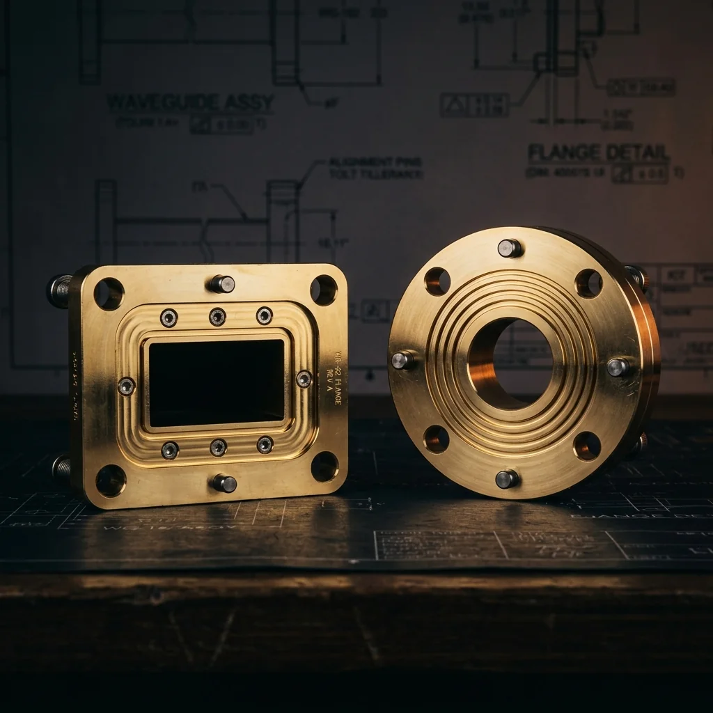
Complete dimensional reference for waveguide choke flanges. Quarter-wave groove specifications, choke joint geometry, and mating requirements. Square choke flanges for S-band through K-band, and round contact choke flanges for K-band through W-band.
Square Choke Flanges
Square choke flanges per MIL-DTL-3922/59. Used for standard rectangular waveguide sizes from WR-284 (S-band) through WR-42 (K-band). Four-hole bolt pattern with quarter-wave choke groove for non-contacting RF seal.
choke groove (S/T diameters), bolt holes, and alignment pins
width (W), flange width (C), and mating surface geometry
• Groove depth (U) = λ/4 at center operating frequency
• Groove creates virtual short circuit at mating interface
• Designed to mate with flat-face cover flanges (NOT with other choke flanges)
• Bolt holes: 4 places, equally spaced at corners
• All dimensions in inches (millimeters)
Square Choke Flange Dimensions
Square choke flange sizes per MIL-DTL-3922/59. Dimensions in inches with millimeter equivalents. Groove depth (U) is calculated as λ/4 at the center operating frequency. Outer mechanical dimensions match the corresponding cover flanges.
| Band | Frequency Band (GHz) |
EIA Waveguide |
K Aperture Width |
L Aperture Height |
C Flange Width |
S Groove Inner Dia |
T Groove Outer Dia |
U Groove Depth (λ/4) |
Choke Flange Designation |
Mates With Cover Flange |
|---|
Round Contact Choke Flanges
Round contact choke flanges per MIL-DTL-3922/71. Used for millimeter-wave waveguide sizes from WR-42 (K-band) through WR-10 (W-band). Circular body with four bolt holes on a bolt circle and quarter-wave choke groove.
choke groove (S/T), bolt circle (N), and alignment pins at 45°
total length (P), and cover flange mating surface
• Groove depth (U) = λ/4 at center operating frequency
• Bolt holes: .112-40 UNC 2B THD, 4 holes equally spaced on bolt circle (N BSC)
• Alignment pins: ø.0615/.0610 (1.56/1.55 mm), 2 each at 45° BSC
• Designed to mate with flat-face cover flanges only
• All dimensions in inches (millimeters)
Round Contact Choke Flange Dimensions
All standard round contact choke flange sizes per MIL-DTL-3922/71. Outer mechanical dimensions (M, N, P, R) match the corresponding cover flanges. Choke groove dimensions (S, T, U) are specific to the choke variant.
| Band | Frequency Band (GHz) |
EIA Waveguide |
K Aperture Width |
L Aperture Height |
M Flange OD |
N Bolt Circle BSC |
S Groove Inner Dia |
T Groove Outer Dia |
U Groove Depth (λ/4) |
Choke Flange Designation |
Mates With Cover Flange |
|---|
What Is a Waveguide Choke Flange?
A waveguide choke flange is a precision-machined interface with a circular quarter-wavelength groove cut into the mating face. This groove creates a "virtual short circuit" at the waveguide junction, effectively containing electromagnetic energy within the waveguide bore without requiring perfect metal-to-metal contact between the mating flanges.
When a choke flange mates with a flat-face cover flange, the quarter-wave groove transforms the open-circuit condition at the outer edge of the groove into a short-circuit condition at the waveguide aperture perimeter. This provides two key advantages: lower RF leakage at the joint, and reduced sensitivity to surface flatness and bolt torque compared to a cover-to-cover connection.
How the Quarter-Wave Groove Works
The choke groove operates as a short section of coaxial transmission line formed between the groove walls and the flat face of the mating cover flange:
- Groove depth (λ/4): The groove is machined to a depth of one quarter of the free-space wavelength at the center operating frequency. This quarter-wave section transforms the open-circuit at the bottom of the groove into a short-circuit at the flange mating surface.
- Groove position: The groove is located concentrically around the waveguide aperture. Its inner diameter is positioned just beyond the waveguide broad wall to intercept any RF energy that leaks past the waveguide-to-flange interface.
- Bandwidth: Because the groove depth is optimized for a single frequency, the choke effectiveness degrades as you move away from the center frequency. However, the performance is typically adequate across the entire recommended operating bandwidth of the waveguide.
Square vs. Round Contact Choke Flanges
- Square Choke Flanges (MIL-DTL-3922/59): Square outer body with four corner bolt holes. Used for larger waveguide sizes from WR-284 (S-band) through WR-42 (K-band). These mate with the corresponding square cover flanges (MIL-DTL-3922/53).
- Round Contact Choke Flanges (MIL-DTL-3922/71): Circular outer body with bolt holes on a bolt circle. Used for millimeter-wave waveguide sizes from WR-42 (K-band) through WR-10 (W-band). These mate with round contact cover flanges (MIL-DTL-3922/67).
Mating Rules
- Choke + Cover = Recommended. This is the standard, intended configuration. The flat cover face closes off the groove, forming the coaxial resonant structure.
- Cover + Cover = Acceptable. Two flat faces can mate, but performance is more sensitive to surface flatness, bolt torque, and alignment.
- Choke + Choke = Not Recommended. Two opposing grooves create a combined depth of λ/2 instead of λ/4, disrupting the short-circuit condition. This typically results in high VSWR and significant RF leakage.
Material and Finish
- Brass (CDA 360): Standard body material. The groove must be machined to tight tolerances with smooth surface finish to maintain the quarter-wave resonance.
- Gold plating: Standard finish for millimeter-wave choke flanges. Critical for the groove surfaces to prevent oxidation that would degrade the choke performance.
- Surface roughness: Groove surfaces typically require 32 microinch Ra or better to maintain low-loss performance at the higher frequency bands.
Frequently Asked Questions
What is a waveguide choke flange?
A choke flange has a circular quarter-wavelength groove machined into its mating face. When it mates with a flat cover flange, the groove creates a virtual short circuit that contains RF energy within the waveguide. This provides lower leakage than a cover-to-cover connection and is less sensitive to surface flatness and torque.
Can I mate two choke flanges together?
No. Mating two choke flanges creates a combined groove depth of λ/2 instead of the required λ/4 short-circuit condition. This results in high VSWR and significant RF leakage. Always mate a choke flange with a flat-face cover flange.
What determines the choke groove depth?
The groove depth is one quarter of the free-space wavelength (λ/4) at the center operating frequency of the waveguide band. For example, at K-band (22.25 GHz center), λ/4 is approximately 0.133 inches (3.38 mm). The exact depth is specified per MIL-DTL-3922 for each waveguide size.
When should I use a choke flange instead of a cover flange?
Use choke flanges when you need lower RF leakage at the joint, when the connection may be subjected to vibration or thermal cycling, or when perfect surface contact cannot be guaranteed. Choke flanges are standard in high-power radar systems, satellite earth stations, and test setups where connection repeatability is important.
Does a choke flange affect insertion loss?
A properly designed choke flange matched with a cover flange typically provides lower insertion loss than a cover-to-cover connection, particularly at millimeter-wave frequencies. The quarter-wave groove compensates for small air gaps and surface imperfections that would otherwise cause reflection losses.