Pressurizable
Flanges
Complete reference for pressurizable (gasket cover) waveguide flanges. O-ring groove dimensions, seal material specifications, pressure ratings, and design guidelines for gas-filled waveguide systems used in high-power radar and satellite earth stations.
Pressurizable Flange Geometry
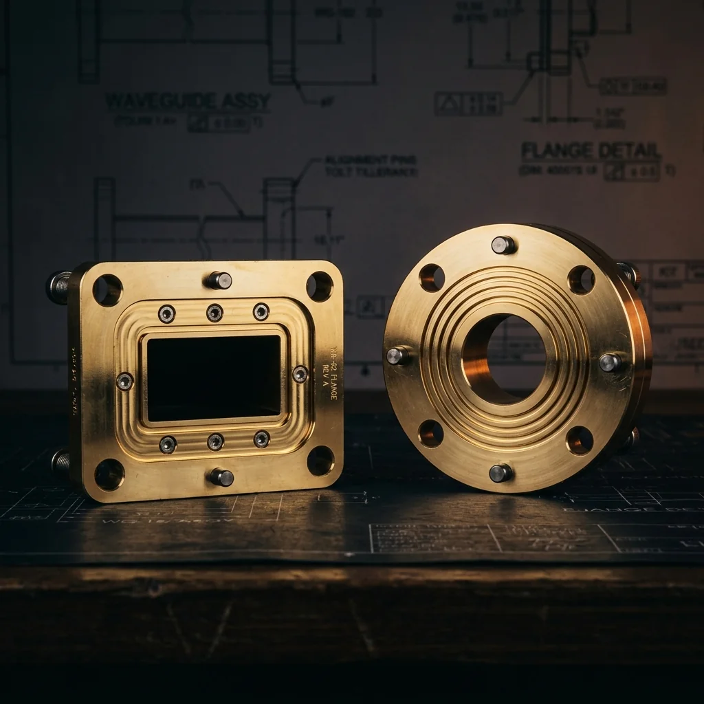
A pressurizable flange (gasket cover) adds a concentric O-ring groove to the standard cover flange mating face. When mated with a flat cover flange, the compressed O-ring creates a gas-tight seal for pressurized waveguide systems.
(S/T diameters), and O-ring cross-section indicators (green)
O-ring squeeze against mating cover flange, and sealed bore
• Groove is concentric with waveguide aperture center
• Groove must be between bolt circle and waveguide aperture to seal the bore
• O-ring squeeze: 20-30% of cross-section for static face seals
• Gland fill: 70-85% maximum (allows for thermal expansion)
• Groove surface finish: 16-32 μin (0.4-0.8 μm) Ra
• Mates with standard flat cover flanges (groove face against flat face)
• All dimensions in inches (millimeters)
Square Pressurizable Flange Dimensions
Square gasket cover flanges for larger waveguide sizes. Outer mechanical dimensions match standard square cover flanges. O-ring groove dimensions (S, T, U, W) are the addition. Standard AS568 O-ring sizes listed for each waveguide.
| Band | Frequency Band (GHz) |
EIA Waveguide |
A Aperture Width |
B Aperture Height |
S Groove ID |
T Groove OD |
U Groove Depth |
W Groove Width |
O-Ring AS568 Dash # |
O-Ring Cross-Section |
Mates With Cover Flange |
|---|
Round Contact Pressurizable Flange Dimensions
Round contact gasket cover flanges for millimeter-wave waveguide sizes. Outer mechanical dimensions match standard round contact cover flanges. Groove dimensions accommodate smaller AS568 O-ring sizes suitable for the compact flange geometry.
| Band | Frequency Band (GHz) |
EIA Waveguide |
K Aperture Width |
L Aperture Height |
M Flange OD |
S Groove ID |
T Groove OD |
U Groove Depth |
W Groove Width |
O-Ring AS568 Dash # |
Mates With Cover Flange |
|---|
O-Ring Material Selection Guide
The choice of O-ring material depends on the operating environment, temperature range, and whether electrical continuity across the flange joint is required.
| Material | Designation | Temp Range | Durometer | Best For |
|---|---|---|---|---|
| Silicone | VMQ | -65°F to +400°F(-54°C to +204°C) | 50-70A | General purpose. Excellent temperature range and low compression set. Standard for most waveguide systems. |
| Fluorosilicone | FVMQ | -75°F to +350°F(-60°C to +177°C) | 50-70A | Fuel/oil resistant environments. Military and aerospace applications. |
| Neoprene | CR | -40°F to +250°F(-40°C to +121°C) | 40-70A | Indoor installations. Good weather and ozone resistance. Lower cost. |
| Viton | FKM | -15°F to +400°F(-26°C to +204°C) | 70-90A | High-temperature and chemical-resistant environments. Excellent for SF6 systems. |
| Conductive Silicone | Ag-VMQ | -65°F to +300°F(-54°C to +149°C) | 50-60A | EMI/RFI shielding required. Silver-filled silicone provides seal and electrical continuity. |
Why Pressurize a Waveguide System?
Waveguide pressurization serves two critical purposes in high-reliability RF systems:
- Moisture prevention: Even a small amount of condensation inside a waveguide can cause significant signal attenuation and corrosion damage. Pressurizing with dry nitrogen or dry air creates a positive internal pressure that prevents moisture-laden ambient air from entering through micro-leaks in the flange joints.
- Power handling: The voltage breakdown threshold in a waveguide increases with gas pressure. For high-power radar transmitters and satellite uplink systems, pressurizing with nitrogen or SF6 (sulfur hexafluoride) can increase the power handling capability by 3x to 10x compared to an unpressurized waveguide at the same altitude.
Groove Design Principles
The O-ring groove in a gasket cover flange is a static axial face seal. Key design parameters:
- Groove location: The groove is concentric with the waveguide aperture and positioned between the aperture and the bolt holes. The groove ID must be large enough to clear the waveguide bore (including any radii), and the groove OD must be small enough to fit inside the bolt pattern.
- Groove depth (U): Calculated to achieve 20-30% compression (squeeze) of the O-ring cross-section when the mating cover flange is bolted into place. Typical groove depth is 70-80% of the O-ring cross-section diameter.
- Groove width (W): Sized at approximately 1.4-1.6 times the O-ring cross-section diameter to provide adequate space for the compressed elastomer without overfilling.
- Surface finish: Groove bottom and walls require 16-32 microinch Ra surface finish for reliable sealing. Rough surfaces can create leak paths along the O-ring contact line.
Common Pressurization Gases
- Dry nitrogen (N2): Most common. Inexpensive, non-toxic, widely available. Typical pressure: 3-5 PSI above ambient. Sufficient for moisture prevention and moderate power handling improvement.
- Dry air (dehydrated): Required to have a dew point below -40°F (-40°C). Common in commercial telecommunications. Supplied by waveguide dehydrator units that continuously pump dried air through the system.
- SF6 (sulfur hexafluoride): Used in high-power applications (ground-based radar, satellite earth stations). Provides 2-3x the dielectric strength of nitrogen at the same pressure. Typical pressure: 15-30 PSI. Environmental regulations are increasingly restricting SF6 use due to its high global warming potential.
Pressure Ratings
- Standard pressure (3-5 PSI / 0.2-0.3 bar): Adequate for moisture prevention in most telecommunications waveguide runs.
- Medium pressure (5-15 PSI / 0.3-1.0 bar): Used for moderate power handling improvement. Requires all flanges to be rated for the pressure.
- High pressure (15-30 PSI / 1.0-2.0 bar): High-power radar and satellite systems using SF6. All gaskets, flanges, and waveguide sections must be rated and periodically leak-tested.
Frequently Asked Questions
What is a pressurizable waveguide flange?
A pressurizable flange (gasket cover) has an O-ring groove on the mating face. When mated with a flat cover flange, the O-ring creates a gas-tight seal that allows the waveguide to be pressurized with dry gas. This prevents moisture and enables higher power handling.
Which face has the O-ring groove?
Only one flange has the groove. The grooved face (gasket cover) mates against a standard flat cover flange. The O-ring sits in the groove and is compressed when the flanges are bolted together. You do not need two grooved flanges; one groove per joint is correct.
What O-ring material should I use?
Silicone (VMQ) for general purpose, fluorosilicone (FVMQ) for military/aerospace, Viton (FKM) for high-temperature or SF6 systems, and silver-filled conductive silicone when EMI shielding is required at the joint. Always verify the material is compatible with the pressurization gas.
What pressure can a gasket cover flange hold?
Standard gasket cover flanges with properly sized O-rings can hold 3-30 PSI depending on the flange size, bolt torque, and O-ring material. For systems above 15 PSI, verify the flange bolt pattern and O-ring cross-section are rated for the pressure. Always leak-test the assembled system before commissioning.
Can I convert a standard cover flange to pressurizable?
Yes, if the flange has sufficient material between the waveguide bore and the bolt holes for the groove. A precision machine shop can cut the O-ring groove into an existing cover flange. Specify the groove dimensions from the table above and the target O-ring size. Ensure the groove surface finish is 32 microinch Ra or better.