Round Contact
Waveguide Flanges
Complete dimensional reference for finished round contact (cover) waveguide flanges. Covers UG-425, UG-381, UG-383, UG-385, and UG-387 designations from WR-42 (K-band) through WR-3 (J-band). All dimensions per MIL-DTL-3922/67 specifications.
Finished Flange and Waveguide
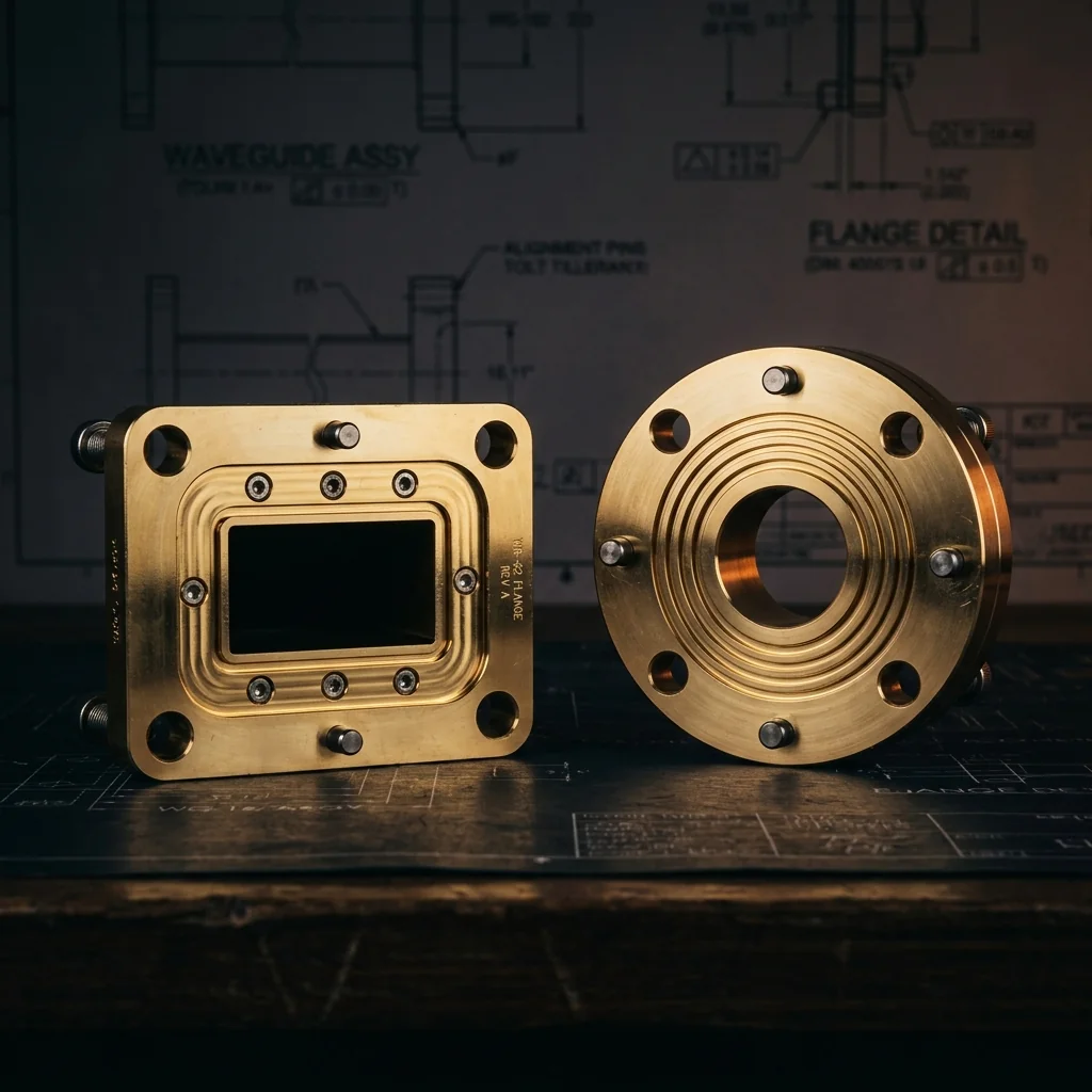
bolt circle (N), flange diameter (M), and alignment pin locations at 45° BSC
flange diameter (M), waveguide bore (K), and alignment pin
• Alignment pins: ø.0615/.0610 (1.56/1.55 mm), 2 each, located at 45° BSC
• Pin hole diameter: ø.068/.067 (1.73/1.70 mm), 2 places
• Bolt holes: .112-40 UNC 2B THD, 4 holes equally spaced on bolt circle
• True position: ⊕ X Y Z ø.004 (.10) relative to datum
• Aperture corner radii: .032 max, .028 min
• All dimensions in inches (millimeters)
Round Contact Flange Dimensions
All standard round contact (cover) waveguide flange sizes per MIL-DTL-3922/67. Dimensions in inches with millimeter equivalents in parentheses. Refer to the technical drawing above for dimension locations.
| Band | Frequency Band (GHz) |
MIL Part # M3922/67 |
K ±.0015 (.04) |
L ±.0015 (.04) |
M ±.000/.002 (.05) |
N BSC |
P ±.005 (.13) |
R ±.005 (.13) |
EIA Waveguide |
Flange Designation |
RF Essentials Flange P/N |
|---|
What Is a Round Contact Waveguide Flange?
A round contact waveguide flange (also called a cover flange or flat flange) is a circular metallic interface that connects two sections of rectangular waveguide. The flange has a flat mating surface with a precisely machined rectangular aperture that matches the waveguide bore, four threaded bolt holes arranged symmetrically on a bolt circle, and two alignment pins that ensure repeatable aperture alignment between mated flanges.
These flanges are manufactured to MIL-DTL-3922/67 (formerly MIL-F-3922/67) specifications and EIA (Electronic Industries Alliance) standards. They are the most common flange type used in millimeter-wave waveguide systems, particularly at frequencies from 18 GHz through 330 GHz.
Dimension Reference
- K (Aperture Width): The broad wall inner dimension of the waveguide aperture. This matches the WR designation (e.g., WR-28 has K = 0.280 inches). Tolerance is ±0.0015 inches (±0.04 mm).
- L (Aperture Height): The narrow wall inner dimension. Typically K/2 for standard aspect ratios. Same tight tolerance as K.
- M (Flange Diameter): The outer diameter of the circular flange body. Two standard sizes exist: 1.125 inches (28.58 mm) for larger waveguides (WR-42 through WR-19) and 0.750 inches (19.05 mm) for smaller waveguides (WR-15 through WR-3).
- N (Bolt Circle): The diameter of the circle on which the four bolt holes are located. This is specified as BSC (basic dimension). Two standard sizes: 0.9375 inches for larger flanges and 0.5625 inches for smaller flanges.
- P (Total Length): The overall length from the flange face to the end of the waveguide stub. This dimension determines how far the waveguide section extends behind the flange.
- R (Flange Thickness): The thickness of the flange body from the mating surface to the back face. Combined with the waveguide stub, this makes up the total length P.
Flange Size Groups
Round contact waveguide flanges fall into two physical size categories based on the waveguide band:
Large Body (M = 1.125", N = 0.9375" BSC)
Used for WR-42 (K-band), WR-28 (Ka-band), WR-22 (Q-band), and WR-19 (U-band). These flanges have a larger bolt circle and flange diameter to accommodate the wider waveguide apertures and provide adequate structural support. The larger P and R dimensions also allow for deeper waveguide bores.
Small Body (M = 0.750", N = 0.5625" BSC)
Used for WR-15 (V-band) through WR-3 (J-band). The reduced flange diameter is both necessary (the waveguide apertures are small enough to fit) and practical (the smaller form factor allows closer component spacing in integrated mmWave assemblies).
Alignment Pin System
Two precision alignment pins are pressed into the flange at 45 degrees from the waveguide broad wall centerline. These pins have a diameter of 0.0615/0.0610 inches (1.56/1.55 mm) and mate with corresponding holes (0.068/0.067 inches diameter) in the opposing flange. The pin-in-hole fit provides repeatable angular and lateral alignment of the waveguide apertures to within the positional tolerance of 0.004 inches (0.10 mm).
Proper alignment is critical at millimeter-wave frequencies because even small misalignments between the waveguide bores introduce reflection loss (increased VSWR) and can excite higher-order modes that degrade system performance.
Material and Finish
- Brass (CDA 360): The standard material for machined flanges. Provides excellent dimensional stability and machinability.
- OFHC Copper: Used for the waveguide section to minimize conductor loss. The flange body may be brass with a copper waveguide insert.
- Gold plating: Standard finish for millimeter-wave flanges. Prevents oxidation of the mating surface, which would increase contact resistance and insertion loss. Typical thickness is 50 to 100 microinches over a nickel barrier.
- Passivation: Stainless steel hardware (screws, pins) is passivated to prevent corrosion.
Frequently Asked Questions
What is a round contact waveguide flange?
A round contact (cover) flange is a circular metallic interface for connecting rectangular waveguide sections. It has a flat mating surface, a rectangular waveguide aperture, four bolt holes, and two alignment pins. It conforms to MIL-DTL-3922/67 and is the standard flange type for millimeter-wave systems from K-band through J-band.
What is the difference between UG-387/U and UG-387/U Flange-M?
UG-387/U is the standard designation. The "-M" suffix (Flange-M) denotes a modified version with adjusted dimensions for specific waveguide sizes. Both share the same 0.750-inch flange diameter and 0.5625-inch bolt circle but differ in the waveguide aperture dimensions (K and L) to match different WR sizes.
Can I mate a round contact flange with a choke flange?
Yes, round contact (cover) flanges are designed to mate with choke flanges. This is the preferred configuration for most connections. The choke flange's quarter-wave groove provides an RF short circuit at the mating interface, reducing leakage. Two cover flanges can also mate together, but with slightly higher sensitivity to surface flatness and torque.
What torque should I use for waveguide flange bolts?
For .112-40 UNC screws on standard round contact flanges, recommended torque is typically 3 to 5 inch-pounds. Over-torquing can warp the flange face, increasing VSWR. Under-torquing allows gaps that cause leakage and impedance mismatch. Always use a calibrated torque wrench and tighten in a cross-pattern.