Square (Flat)
Flanges
Complete dimensional reference for square flat (cover) waveguide flanges. Finished bore dimensions, bolt patterns, alignment pin locations, and body specifications per MIL-DTL-3922/1. Covers standard sizes from WR-284 (S-band) through WR-42 (K-band).
Square Cover Flange Geometry
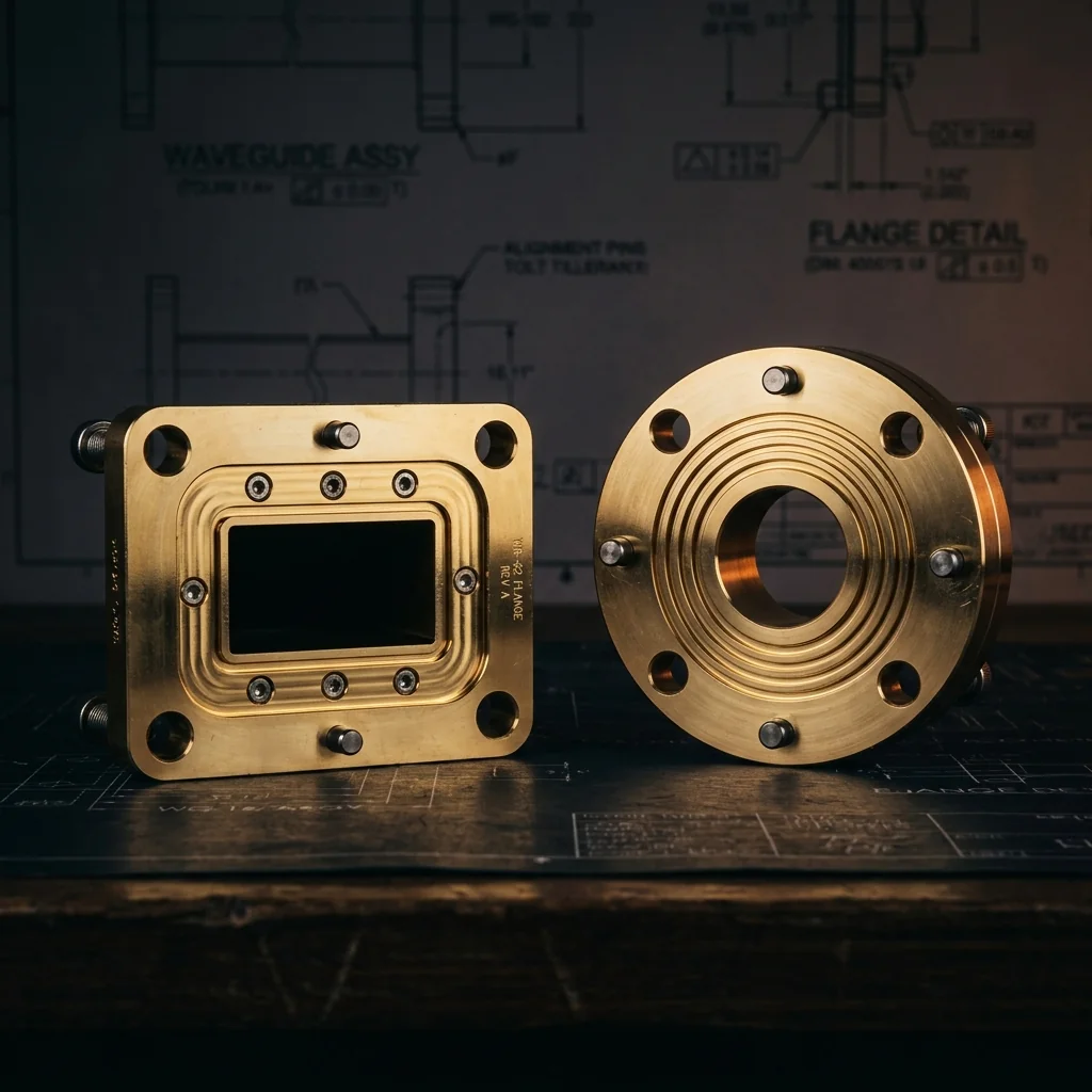
Standard square flat (cover) flanges per MIL-DTL-3922/1. Four-hole bolt pattern with circular back register. Flat mating face with precision-machined waveguide aperture. Used for standard rectangular waveguide from WR-284 (S-band) through WR-42 (K-band).
bolt hole spacing (F BSC), circular back (G), and alignment pins
flange plate thickness (E), total length (D), and step height (H)
• Waveguide aperture (A × B) machined to finished dimensions per MIL-DTL-3922
• Bore tolerance: ±.002 (.05) on A and B for standard flanges
• Flatness: .0005 (.013) maximum across mating surface
• Surface finish: 63 μin (1.6 μm) Ra or better on mating face
• Bolt holes: 4 places, equally spaced at corners
• Edge chamfer: .12 (.30) x 45°
• Alignment pins: 2 each, diagonally opposite
• All dimensions in inches (millimeters)
Square Cover Flange Dimensions
All standard square flat (cover) flange sizes per MIL-DTL-3922/1. Dimensions in inches with millimeter equivalents. Aperture dimensions (A, B) are finished bore sizes with tight tolerances. Refer to the drawing above for dimension locations.
| Band | Frequency Band (GHz) |
EIA Waveguide |
A ±.002 (.05) |
B ±.002 (.05) |
C Flange Width |
D Total Length |
E Plate Thickness |
F Bolt Spacing BSC |
G Circ. Back Dia |
H Step Height |
Flange Designation |
Mates With Choke Flange |
|---|
• A, B = Finished waveguide aperture (bore) width and height
• C = Flange body width/height (square)
• D = Total length (mating face to back)
• E = Flange plate thickness at bolt holes
• F = Bolt hole spacing (center-to-center, BSC)
• G = Circular back register diameter
• H = Step/boss height behind flange plate
• "Mates With" column shows the corresponding choke flange designation
What Is a Square Flat Flange?
A square flat flange, also called a cover flange, is the standard waveguide interface for larger rectangular waveguide sizes. It consists of a square metallic plate with a precision-machined rectangular waveguide aperture (bore) at the center, four bolt holes at the corners for mechanical fastening, and a circular back register for alignment with the waveguide tube.
The mating face is flat and smooth, with no grooves or cavities. When two cover flanges are bolted together, they rely on surface flatness and bolt torque to create a good electrical connection at the waveguide junction. For improved RF sealing, a cover flange is typically mated with a choke flange that has a quarter-wave groove.
When to Use Square Flanges
Square flat flanges are the standard interface for waveguide sizes from WR-284 (S-band, 2.60 GHz) through WR-42 (K-band, 26.5 GHz). At WR-42 and smaller, the industry transitions to round contact flanges (MIL-DTL-3922/67) which have a circular outer body optimized for the small physical size of millimeter-wave waveguide.
- WR-284 through WR-42: Square flat flanges (this page)
- WR-42 through WR-3: Round contact flanges
- WR-42: Available in both square and round contact configurations
Mating Combinations
- Cover + Choke = Best. Standard configuration. The flat cover face closes off the choke groove, creating the quarter-wave resonant seal. Lowest leakage and best VSWR.
- Cover + Cover = Acceptable. Simple and common for non-critical connections. Performance depends on surface flatness and bolt torque. Adequate for most lab and field applications.
- Choke + Choke = Avoid. Two opposing grooves create a half-wave cavity that disrupts the short-circuit condition. High VSWR and excessive leakage.
Bolt Pattern and Alignment
All square flat flanges use a four-hole bolt pattern at the corners. The bolt hole spacing (F BSC) scales with the waveguide size. Alignment is provided by two dowel pins located diagonally opposite each other. The circular back register (G diameter) centers the waveguide tube concentrically with the flange aperture.
- Large WR sizes (WR-284, WR-187): Bolt holes are typically through-holes for use with machine screws and nuts.
- Medium WR sizes (WR-137 through WR-62): Bolt holes may be tapped (threaded) or through depending on the specific application.
- WR-42: Bolt holes are typically .147 DIA THRU or .144 DIA THRU.
Material and Surface Finish
- Brass (CDA 360): Standard body material. Excellent machinability and corrosion resistance.
- Aluminum (6061-T6): Used for lightweight applications, particularly in airborne systems. May require additional surface treatment for corrosion protection.
- Gold plating: Standard finish for precision flanges. Prevents oxidation and ensures consistent electrical contact at the mating surface.
- Mating surface flatness: Typically .0005 inches (0.013 mm) maximum deviation across the full face for standard grades.
Frequently Asked Questions
What is a square flat flange?
A square flat (cover) flange is a standard waveguide interface with a square outer body, four bolt holes, and a precision-machined rectangular aperture. The flat mating face provides a contact seal when bolted to another flange. Square flanges are used for larger waveguide sizes from WR-284 (S-band) through WR-42 (K-band).
What does UG stand for in flange designations?
UG is a legacy military designation (United States Government / Universal Guide) that identifies a specific flange interface. Each UG number defines the exact dimensions, bolt pattern, and waveguide size. For example, UG-135/U is the standard cover flange for WR-90 (X-band) waveguide.
What is the difference between a cover and a choke flange?
A cover flange has a smooth, flat mating face. A choke flange has a quarter-wave groove that creates a virtual short circuit for better RF sealing. Cover flanges are simpler and less expensive. The standard practice is to mate a choke with a cover for the best performance, but cover-to-cover is acceptable for most applications.
Can I use a square flange on WR-42 waveguide?
Yes. WR-42 is available in both square (UG-595/U, MIL-DTL-3922/1) and round contact (UG-425/U, MIL-DTL-3922/67) configurations. The choice depends on the mating equipment. Most K-band systems use the round contact interface, but square flanges are still used in some legacy and custom systems.
What torque should I use when bolting flanges?
Typical bolt torque for waveguide flanges is 8 to 12 inch-pounds for smaller sizes (WR-62, WR-42) and 15 to 25 inch-pounds for larger sizes (WR-90 through WR-284). Over-torquing can warp the flange face, degrading the RF connection. Under-torquing allows air gaps that increase leakage. Use a calibrated torque wrench and follow the manufacturer's specifications.