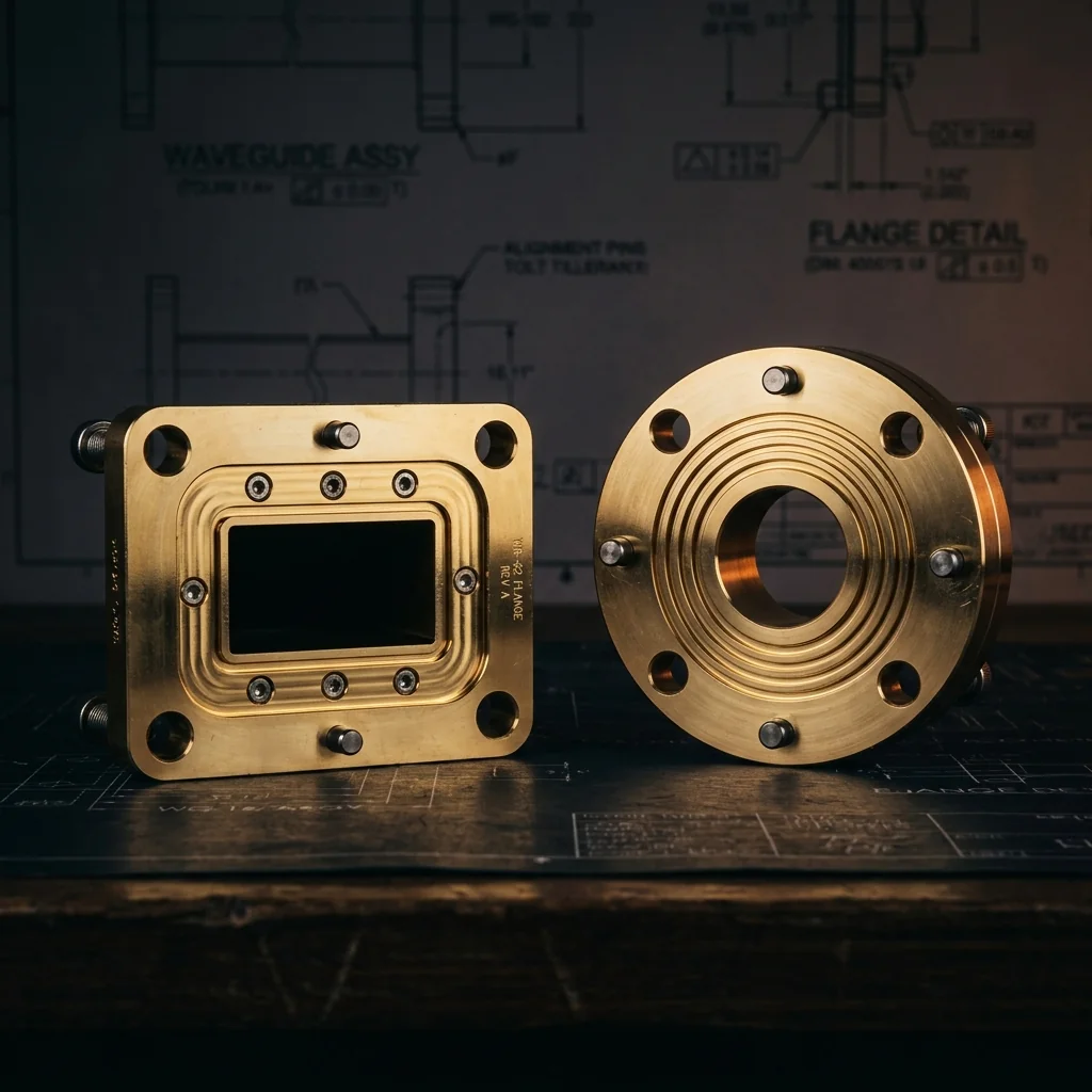
Waveguide
Flange Blanks
Complete dimensional reference for waveguide flange blanks. Square cover blanks per MIL-DTL-3922/53 for S-band through K-band, and round contact blanks per MIL-DTL-3922/67 for K-band through J-band. Pilot bore specifications, bolt patterns, and tolerances for all standard sizes.
Square Cover Flange Blanks
Square cover flange blanks per MIL-DTL-3922/53. Used for standard rectangular waveguide sizes from WR-284 (S-band) through WR-42 (K-band). Four-hole bolt pattern with oversized pilot bore for customer finish machining.
circular back diameter (G), and optional alignment pin holes
flange thickness (E), step height (H), and pilot bore
• Bolt holes: F Hole, 4 places, equally spaced at corners
• Circular back: G diameter (concentric with aperture center)
• True position: ⊕ X Y Z ø.001 (.02) relative to datum
• Edge chamfer: .12 (.30) x 45°
• Pilot bore corners: .032/.028 max radius
• Flange can be ordered with or without holes for alignment pins
• All dimensions in inches (millimeters)
Square Cover Flange Blank Dimensions
Square cover flange blank sizes per MIL-DTL-3922/53. Dimensions in inches with millimeter equivalents. Pilot bore dimensions (A, B) are intentionally oversized for customer finish machining. Refer to the drawing above for dimension locations.
| Band | Frequency Band (GHz) |
EIA Waveguide |
MIL Part # M3922/53 |
A ±.002 (.05) |
B ±.002 (.05) |
C .015 (.38) |
D BSC |
E BSC |
F ±.003 (.08) |
G ±.015 (.38) |
H ±0.15 (.38) |
J ±.015 (.38) |
Flange Designation |
|---|
• A, B = Pilot bore width and height (oversized for finish machining)
• C = Flange body width/height (square)
• D = Total length (flange face to back)
• E = Flange plate thickness
• F = Bolt hole spacing (center-to-center)
• G = Circular back diameter
• H = Step/boss height behind flange plate
• J = Step/boss diameter or width
Round Contact Flange Blanks
Round contact (cover) flange blanks per MIL-DTL-3922/67. Used for millimeter-wave waveguide sizes from WR-42 (K-band) through WR-3 (J-band). Circular body with four bolt holes on a bolt circle, oversized pilot bore for customer finish machining.
4 bolt holes, and optional alignment pin holes at 45° BSC
flange thickness (E), pilot bore, and chamfer detail
• Bolt holes: .112-40 UNC 2B THD, 4 holes equally spaced on bolt circle (F BSC)
• True position: ⊕ X Y Z ø.004 (.10) relative to datum
• Edge chamfer: .010 (.25) x 45°
• Flatness: .006 Max. Typ. (datum Y)
• Parallelism: Z .002
• Pilot bore corners: .032/.028 max radius
• Flange can be ordered with or without holes for alignment pins
• All dimensions in inches (millimeters)
Round Contact Flange Blank Dimensions
All standard round contact (cover) flange blank sizes per MIL-DTL-3922/67. Dimensions in inches with millimeter equivalents. Pilot bore dimensions (A, B) are intentionally oversized for customer finish machining.
| Band | Frequency Band (GHz) |
EIA Waveguide |
MIL Part # M3922/67 |
A +.002/-.000 (.05) |
B +.002/-.000 (.05) |
C +.000/-.002 (.05) |
D ±.005 (.13) |
E ±.005 (.13) |
F BSC |
Flange Designation |
|---|
What Is a Waveguide Flange Blank?
A waveguide flange blank is a precision-machined metallic component with the bolt pattern, alignment features, and basic profile of a finished waveguide flange, but without the final waveguide aperture (bore) machined to finished dimensions. Instead, the blank contains an oversized pilot bore that provides a starting point for the customer or integrator to machine the waveguide aperture to their exact specifications.
Flange blanks are used when the application requires a non-standard bore size, a custom waveguide transition, tighter-than-standard aperture tolerances, or integration into a proprietary component design. The blank provides the mechanical interface (bolt pattern, alignment features, outer dimensions) while allowing full control over the critical RF aperture dimensions.
Square vs. Round Contact Blanks
Two distinct flange blank styles exist, each serving different frequency ranges and waveguide sizes:
- Square Cover Flange Blanks (MIL-DTL-3922/53): Have a square outer body with four corner bolt holes. Used for larger waveguide sizes from WR-284 (S-band, 2.60 GHz) through WR-42 (K-band, 26.5 GHz). These flanges have a circular back (register) that centers the flange on the mating surface. Standard bolt hole thread is typically .147 DIA THRU or .144 DIA THRU depending on waveguide size.
- Round Contact Flange Blanks (MIL-DTL-3922/67): Have a circular outer body with four bolt holes equally spaced on a bolt circle. Used for smaller millimeter-wave waveguide sizes from WR-42 (K-band, 18.0 GHz) through WR-3 (J-band, 330 GHz). Standard bolt hole thread is .112-40 UNC 2B.
WR-42 (K-band) overlaps both types. The choice depends on the mating equipment and system architecture.
Pilot Bore Oversize
The pilot bore dimensions A and B are calculated to provide sufficient material for the customer to machine the final waveguide aperture. The oversize amount varies by waveguide size:
- Large waveguides (WR-284 through WR-62): Pilot bore is approximately 0.060 to 0.100 inches larger than the finished waveguide aperture in each dimension, providing roughly 0.030 to 0.050 inches of material per side for finish machining.
- Millimeter-wave waveguides (WR-42 through WR-3): Pilot bore oversize is approximately 0.060 to 0.082 inches depending on the waveguide size, with smaller oversize at higher frequencies where tighter dimensional control is required.
Ordering Options
Flange blanks can be ordered in two configurations:
- With alignment pin holes: The alignment pin holes are pre-drilled per the applicable MIL-DTL-3922 specification. This is the standard configuration for applications that will use the standard pin locations.
- Without alignment pin holes: The blank has no pin holes, allowing the integrator to drill the pin holes after machining the waveguide bore. This ensures the pins are positioned precisely relative to the custom bore, which is critical for non-standard aperture sizes.
Material and Finish
- Brass (CDA 360): Standard material for flange blanks. Provides excellent machinability for the customer's finish boring operation.
- Gold plating: Blanks are typically supplied un-plated (bare brass) since the customer will perform additional machining. Gold plating is applied after final boring of the waveguide aperture.
- Custom materials: OFHC copper, aluminum, and stainless steel blanks are available on request for special applications.
Frequently Asked Questions
What is a waveguide flange blank?
A flange blank is an un-bored flange with the correct outer dimensions, bolt holes, and basic profile, but without the final waveguide aperture. The blank includes an oversized pilot bore for the customer to machine to exact waveguide dimensions. Blanks can be ordered with or without alignment pin holes.
What is the difference between square and round contact blanks?
Square blanks (MIL-DTL-3922/53) have a square outer body with corner bolt holes and are used for larger waveguide sizes (WR-284 through WR-42). Round contact blanks (MIL-DTL-3922/67) have a circular body with bolt holes on a bolt circle and are used for millimeter-wave sizes (WR-42 through WR-3). The choice depends on the mating equipment and frequency range.
Why use a flange blank instead of a finished flange?
Flange blanks give the integrator full control over the waveguide aperture dimensions. This is essential for non-standard bore sizes, custom waveguide transitions, tapered apertures, or when tighter-than-standard tolerances are required. Blanks are also used in R&D prototyping where the final bore dimensions may need adjustment.
What tolerance can I hold when boring a flange blank?
The pilot bore in the blank has a unilateral positive tolerance (+.002/-.000 inches) to ensure adequate material for finish machining. When boring the final aperture, most precision shops can hold ±0.0005 to ±0.001 inches on the waveguide dimensions, which is tighter than the standard ±0.0015 inches specified for production flanges.
Should I order blanks with or without alignment pin holes?
If you are machining a standard WR-size aperture, order with pin holes for convenience. If you are machining a non-standard bore or need the pins positioned precisely relative to a custom aperture, order without pin holes and drill them after final boring.