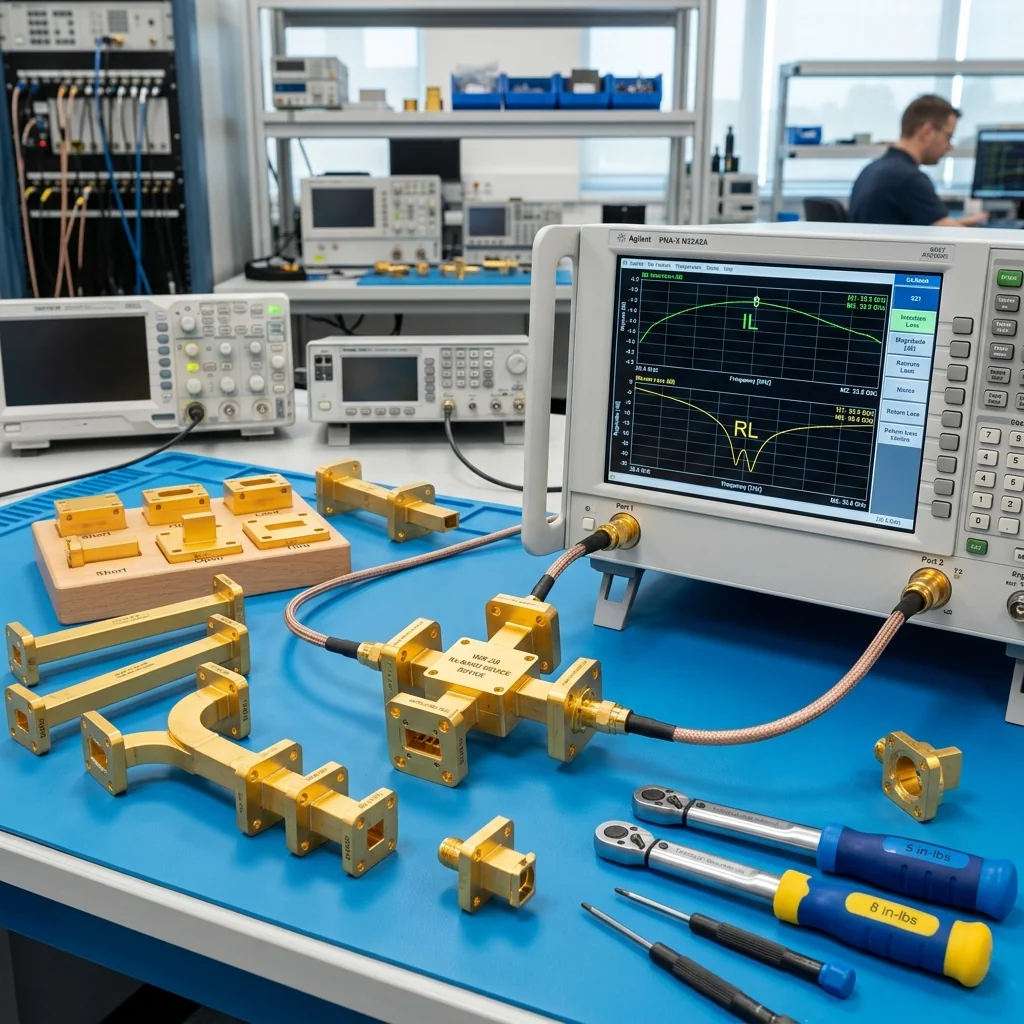
A shipment of waveguide components arrives at your lab: straight sections, bends, terminations, adapters, perhaps a custom filter assembly. The packing list says they meet specification. The data sheets list impressive numbers. But until you connect each piece to a calibrated vector network analyzer and verify the insertion loss and VSWR yourself, those numbers are promises, not measurements. Incoming inspection is not optional for any organization building systems where RF performance determines mission success. This guide walks through the complete verification procedure, from unpacking through calibration to final acceptance, with specific attention to the pitfalls that produce misleading results.
Before You Power Up: Physical Inspection
Start with the waveguide flanges. Examine each flange face under a 10x magnifier for scratches, dents, burrs, or contamination across the aperture and sealing surface. A scratch across the broad wall of a WR-28 aperture (7.112 mm wide) that is 0.05 mm deep may seem minor, but at 33 GHz it creates a discontinuity that can degrade return loss by 5 to 10 dB. Check that alignment pins (for UG-style flanges) or alignment holes (for CPR/CMR flanges) are present, undamaged, and properly seated. Verify that the waveguide bore is clean and free of machining debris; a small aluminum chip lodged inside a WR-42 straight section can produce a resonant reflection that appears as a narrow notch in the S21 response.
Inspect the flange gasket surfaces for flatness. Place the flange face-down on a precision surface plate and check for rocking. Any visible gap indicates a warped flange that will not seal properly against its mating flange, creating a gap that acts as a series capacitance and degrades return loss at higher frequencies. For critical applications, use a flatness gauge; the specification for a standard UG-599/U flange is 0.025 mm (0.001 inch) maximum deviation.
VNA Calibration: Getting the Reference Right
The accuracy of your waveguide measurements is entirely determined by the quality of your calibration. A poorly executed calibration will mask defects or, worse, falsely flag good components as failures. For waveguide measurements, use a TRL (Thru-Reflect-Line) calibration, which is inherently more accurate than SOLT (Short-Open-Load-Thru) at waveguide frequencies because TRL does not require a broadband matched load, which is difficult to manufacture with consistent performance across a full waveguide band.
| Cal Standard | Function | Critical Specification | Common Failure Mode |
|---|---|---|---|
| Thru | Defines zero insertion loss and phase | Flange alignment; zero-length or known-length | Contaminated flange face; incorrect length entry |
| Reflect (short) | Defines perfect reflection reference | Return loss > 50 dB; flat phase vs. frequency | Worn plunger; damaged aperture edge |
| Line (offset short or λ/4) | Provides phase separation from thru | Known length ± 0.01 mm; clean bore | Wrong line length for frequency band |
| Load (for SOLT) | Defines matched reference impedance | Return loss > 40 dB across band | Degraded absorber; temperature-dependent RL |
Set the VNA frequency range to cover the full waveguide band with at least 201 points (401 is preferred for components with sharp features like filters). Set the IF bandwidth to 100 Hz for production measurements or 10 Hz for high-accuracy characterization. Apply power leveling if available; the VNA source power should be -10 to 0 dBm for passive component measurement, low enough to avoid nonlinear effects in ferrite components but high enough to keep the measurement above the noise floor.
Insertion Loss Measurement: Reading S21 Correctly
After calibration, connect the device under test (DUT) between the VNA ports. Apply the manufacturer-specified torque to all flange bolts using a calibrated torque wrench. For UG-style flanges with four 4-40 bolts, the standard torque is 5 to 7 inch-pounds. Over-torquing warps the flange; under-torquing leaves a gap. Both produce measurement errors that look like component defects.
Insertion Loss Budget for a WR-28 Straight Section (6 inches): Theoretical waveguide attenuation (copper, TE10 mode): 0.053 dB/inch at 33 GHz = 0.32 dB for 6 inches. Flange-to-flange connection loss: 0.01 to 0.03 dB per connection × 2 = 0.02 to 0.06 dB. Surface finish contribution: add 10 to 20% for typical CNC finish (32 μin Ra). Expected total IL: 0.35 to 0.42 dB. Acceptance criterion: < 0.50 dB (manufacturer spec with margin). If measured IL exceeds 0.50 dB, investigate: check connections, re-torque, re-calibrate. If IL exceeds 1.0 dB, suspect internal damage or manufacturing defect.
Read S21 as magnitude in dB across the full band. For a straight section, the insertion loss should increase monotonically with frequency (since waveguide attenuation increases with frequency) with no sharp dips or resonances. A sharp notch in S21 at a specific frequency indicates an internal obstacle creating a resonant reflection. A gradual ripple in S21 (sinusoidal variation with frequency) indicates an impedance mismatch at one or both flanges, creating a standing wave between the mismatch point and the VNA calibration reference plane.
For bends, expect 0.03 to 0.10 dB of additional insertion loss beyond the straight-section equivalent length. For E-plane bends at WR-28, the typical specification is less than 0.15 dB of total insertion loss. H-plane bends generally have slightly higher loss than E-plane bends of the same radius due to the current flow disruption on the broad wall.
VSWR and Return Loss: Reading S11 and S22
Measure S11 (return loss at port 1 with port 2 terminated) across the full band. For precision waveguide components, the acceptance criterion is typically VSWR < 1.05:1 (return loss > 32 dB) for straight sections and VSWR < 1.10:1 (return loss > 26 dB) for bends and transitions. Convert between VSWR and return loss using the standard relationship:
| VSWR | Return Loss (dB) | Reflected Power | Typical Component |
|---|---|---|---|
| 1.02:1 | 40.1 | 0.01% | Premium straight section |
| 1.05:1 | 32.3 | 0.06% | Standard straight section |
| 1.10:1 | 26.4 | 0.23% | Bend, twist, transition |
| 1.15:1 | 23.1 | 0.47% | Adapter, waveguide-to-coax |
| 1.20:1 | 20.8 | 0.83% | Filter passband edge |
| 1.50:1 | 14.0 | 4.0% | Reject (investigate) |
When measuring return loss, the termination on the opposite port matters. Use a precision waveguide termination with return loss better than 40 dB. If the far-end termination has only 30 dB of return loss, reflections from the termination travel through the DUT and add vectorially to the DUT's own return loss, creating measurement errors that oscillate with frequency. The ripple amplitude is proportional to the termination reflection coefficient multiplied by the DUT's transmission coefficient squared.
Measurement Uncertainty and Repeatability
Every waveguide measurement has uncertainty from three primary sources: VNA instrument uncertainty (typically ±0.02 to 0.05 dB for insertion loss), calibration standard uncertainty (dependent on the standards' certified accuracy), and connector repeatability (the variation observed when disconnecting and reconnecting the DUT). Connector repeatability is often the dominant source, contributing 0.01 to 0.05 dB of insertion loss variation and 2 to 5 dB of return loss variation per connection cycle.
To establish your measurement system's repeatability, perform a gauge R&R study: measure the same component 10 times, disconnecting and reconnecting between each measurement. Calculate the standard deviation of S21 and S11 at the center of the band. Multiply by 2 for a 95% confidence interval. This is your measurement system's repeatability contribution to the uncertainty budget. If the repeatability exceeds half of the acceptance tolerance, your measurement system cannot reliably distinguish passing from failing components, and you need to improve your calibration, connection technique, or torque procedure.
At RF Essentials, every waveguide component we ship includes measured S-parameter data traceable to our calibrated VNA and NIST-traceable calibration standards. When our customers perform incoming inspection and compare their measurements to our shipped data, the correlation validates both measurement systems and provides confidence that the component will perform as specified in the final assembly. That traceability chain, from our measurement lab to yours, is what separates verified performance from catalog promises.
Every RF Essentials waveguide component ships with measured S-parameter data. Our product line includes straight sections, bends, twists, terminations, adapters, and calibration standards from WR-03 through WR-430.
Frequently Asked Questions
What should I check before electrically testing a received waveguide component?
Start with physical inspection. Examine each flange face under a 10x magnifier for scratches, dents, burrs, or contamination, since a 0.05 mm scratch across a WR-28 aperture can degrade return loss by 5 to 10 dB at 33 GHz. Confirm alignment pins or holes are undamaged, the bore is clean and free of machining debris, which can cause a resonant notch, and the flange face is flat within 0.025 mm against a precision surface plate.
How do I tell whether a waveguide's measured insertion loss is acceptable?
Build a budget. A 6-inch WR-28 straight section at 33 GHz has about 0.32 dB of theoretical attenuation, plus 0.02 to 0.06 dB of flange connection loss, plus 10 to 20 percent for typical surface finish, so expect 0.35 to 0.42 dB against a 0.50 dB specification. If the measured loss exceeds 0.50 dB, check connections, re-torque, and re-calibrate. Above 1.0 dB, suspect internal damage, and the loss should rise smoothly with frequency.
What do ripple or a sharp notch in the S21 trace indicate?
A sharp notch at a single frequency means an internal obstacle, often debris or a defect, creating a resonant reflection inside the waveguide. A gradual sinusoidal ripple versus frequency means an impedance mismatch at one or both flanges, creating a standing wave between that mismatch and the VNA calibration reference plane. Reading the shape of the S21 curve tells you whether the problem is internal to the part or at the connection.