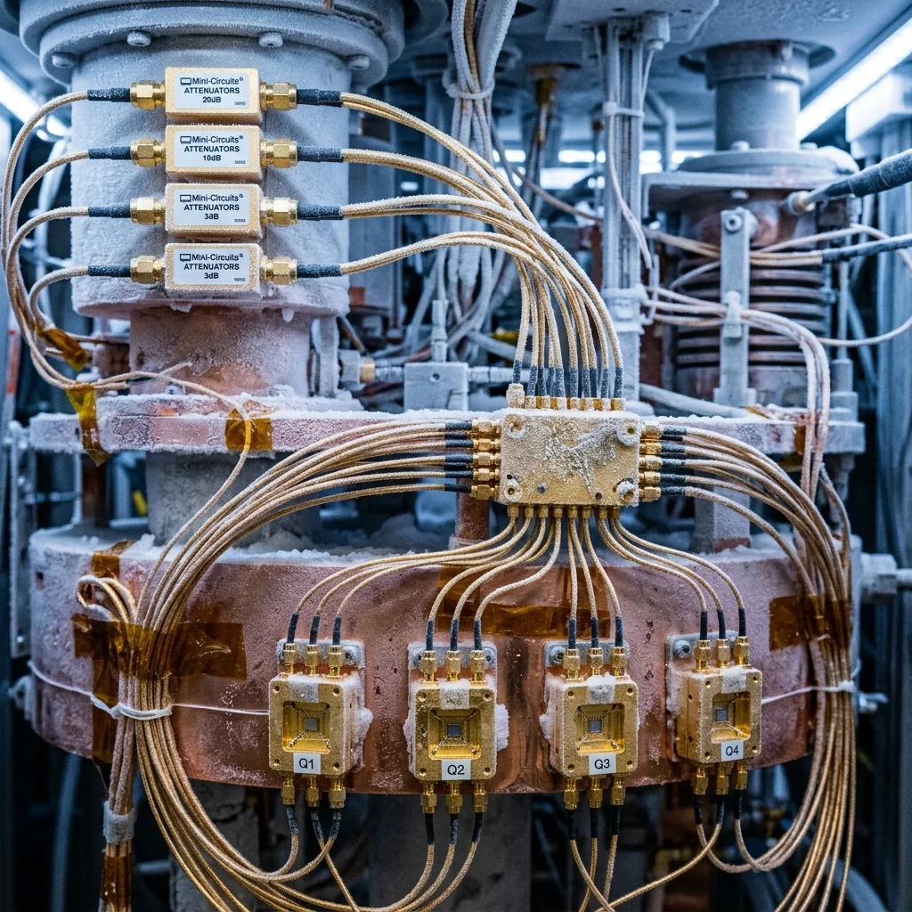
Scaling a superconducting quantum processor from 100 qubits to 1,000 or 10,000 presents a wiring crisis. Every qubit requires a dedicated readout resonator, and every readout resonator traditionally requires its own coaxial line running from the mixing chamber at 10 millikelvin up through the dilution refrigerator's thermal stages to room-temperature electronics. Each coaxial line conducts heat, adds mass, and consumes physical space in a cryostat that has finite cooling power and finite feedthrough capacity. At 100 qubits, the wiring is dense but manageable. At 1,000 qubits with individual readout lines, the refrigerator cannot maintain base temperature. Frequency-division multiplexing (FDM) solves this by assigning each readout resonator a unique frequency and combining multiple resonator signals onto a single coaxial line, reducing the wiring count by factors of 10 to 100.
Dispersive Readout: The Foundation
Before understanding multiplexing, the single-qubit dispersive readout must be clear. Each transmon qubit is capacitively coupled to a superconducting coplanar waveguide (CPW) resonator with a resonant frequency in the 4 to 8 GHz range. In the dispersive regime, where the qubit-resonator detuning is much larger than their coupling strength, the qubit state shifts the resonator frequency by an amount called the dispersive shift, χ. When the qubit is in state |0⟩, the resonator sits at frequency fr. When the qubit is in state |1⟩, the resonator shifts to fr + 2χ, where χ typically ranges from 0.5 to 5 MHz.
Readout proceeds by sending a microwave probe tone at or near fr and measuring the transmitted or reflected signal. The phase and amplitude of the return signal differ depending on the qubit state, because the resonator's response curve has shifted. The signal-to-noise ratio of this measurement determines the readout fidelity: how accurately the measurement distinguishes |0⟩ from |1⟩. Current state-of-the-art systems achieve single-shot readout fidelity above 99% in 200 to 500 ns measurement time.
Dispersive Readout SNR: SNR = (2χ / κ)2 × η × n̄ × κ × Tmeas, where χ = dispersive shift, κ = resonator linewidth, η = measurement chain efficiency, n̄ = average photon number in the resonator, Tmeas = measurement integration time. For χ/2π = 2 MHz, κ/2π = 5 MHz, η = 0.3, n̄ = 5, Tmeas = 500 ns: SNR ≈ 12 (fidelity > 99%). The constraint: n̄ cannot exceed the critical photon number ncrit = (Δ/2g)2 without inducing qubit state transitions, typically limiting n̄ to 1 to 20 photons.
Frequency-Division Multiplexing Architecture
In FDM readout, N readout resonators are designed with equally spaced resonant frequencies across a bandwidth window, typically 4 to 8 GHz. If the channel spacing is 20 MHz and the available bandwidth is 4 GHz, up to 200 resonators can share a single feedline. In practice, channel counts of 10 to 20 per line are common in current processors, with research demonstrations reaching 40 to 72 channels per line.
All resonators couple to a common transmission line (the feedline) through small coupling capacitors. A readout pulse containing N simultaneous tones, one per resonator, is sent down the feedline. Each tone interacts with its corresponding resonator and picks up a phase shift determined by that qubit's state. The return signal, containing all N tones superimposed, travels back up the single coaxial line to the amplification chain. At room temperature, digital signal processing separates the individual tones and extracts the qubit state from each.
| Parameter | Single-Channel | FDM (current) | FDM (target) |
|---|---|---|---|
| Channels per line | 1 | 10 to 20 | 50 to 200 |
| Channel spacing | N/A | 50 to 100 MHz | 10 to 20 MHz |
| Bandwidth required | ~20 MHz | 0.5 to 2 GHz | 2 to 4 GHz |
| Coax lines for 1000 qubits | 1000 | 50 to 100 | 5 to 20 |
| Heat load per line (10 mK) | ~0.5 μW | ~0.5 μW | ~0.5 μW |
| Total heat load (1000 qubits) | 500 μW | 25 to 50 μW | 2.5 to 10 μW |
| Readout fidelity | > 99.5% | > 99% | > 98% (goal) |
Channel Spacing and Crosstalk Constraints
The minimum channel spacing in FDM readout is determined by several factors. The resonator linewidth κ sets the fundamental limit; channels must be separated by several κ to avoid spectral overlap. For a resonator with κ/2π = 5 MHz, a minimum spacing of 20 to 30 MHz prevents significant overlap between adjacent channels. The dispersive shift 2χ must also be considered, since the resonator frequency shifts by up to 2χ depending on qubit state; channel spacing must accommodate this shift without encroaching on the neighbor's frequency band.
Fabrication variations add additional margin requirements. Lithographic tolerances in CPW resonator fabrication produce frequency scatter of 5 to 20 MHz across a chip, depending on the process maturity. If two resonators designed 30 MHz apart land 10 MHz closer due to process variation, their channels may overlap. This drives practical channel spacing to 50 to 100 MHz in current production processors, even though the theoretical minimum is much smaller.
Crosstalk between channels also arises from nonlinearity in the readout chain. When N tones pass through a quantum-limited amplifier, intermodulation products appear at sum and difference frequencies. If these products land on another channel's frequency, they corrupt that measurement. Keeping the per-channel power low (typically -130 to -120 dBm at the resonator) minimizes intermodulation but reduces SNR, requiring longer integration times or better amplifiers to maintain fidelity.
The Cryogenic Amplification Chain
The amplification chain is the performance bottleneck for multiplexed readout. The signal leaving the mixing chamber contains N readout tones, each at approximately -130 dBm (a few photons' worth of energy). This signal must be amplified by 80 to 100 dB before it can be digitized at room temperature. The first amplifier in the chain determines the system noise temperature and therefore the readout SNR.
Josephson parametric amplifiers (JPAs) provide near-quantum-limited noise performance (noise temperature of 50 to 100 mK, corresponding to approximately half a photon of added noise) but have limited bandwidth, typically 10 to 50 MHz. This restricts JPA-based readout to single-channel or few-channel multiplexing. For wideband FDM, traveling-wave parametric amplifiers (TWPAs) are the enabling technology. A TWPA based on Josephson junction arrays or kinetic inductance nonlinearity provides 15 to 20 dB of gain across 3 to 8 GHz of bandwidth with near-quantum-limited noise, enough to amplify 50 or more multiplexed channels simultaneously.
Following the TWPA, a cryogenic HEMT amplifier at the 4 K stage provides an additional 30 to 40 dB of gain with a noise temperature of 2 to 5 K. Because the TWPA has already amplified the signal above the HEMT's noise floor, the HEMT's relatively high noise temperature does not degrade the system performance. Room-temperature amplifiers add the remaining 30 to 40 dB of gain before the signal enters the digitizer. The entire chain must maintain amplitude flatness across the multiplexed bandwidth to ensure uniform readout fidelity across all channels. Precision terminations at unused ports of cryogenic circulators and directional couplers prevent reflections that would create standing waves and channel-dependent gain ripple.
Scaling Challenges Beyond 100 Channels
Pushing FDM beyond 100 channels per line introduces new challenges. The multi-tone readout pulse requires a DAC with enough bandwidth and dynamic range to synthesize 100+ simultaneous tones without intermodulation. Current FPGA-based arbitrary waveform generators can produce 2 to 4 GHz of analog bandwidth with 14-bit resolution, sufficient for approximately 100 channels at 20 MHz spacing. Reaching 200+ channels requires either wider-bandwidth DACs or multiple DAC channels that are coherently combined.
On the digitizer side, the return signal containing 100+ tones must be captured by an ADC with sufficient bandwidth, dynamic range, and sampling rate to resolve all channels simultaneously. The processing burden for real-time tone separation, state discrimination, and error correction at 100+ channels pushes the limits of current FPGA architectures. Several quantum computing companies are developing custom ASICs specifically for multiplexed readout signal processing.
Cryogenic-compatible waveguide terminations and attenuator pads serve as matched loads and signal conditioning elements within the dilution refrigerator's microwave chain. The dimensional stability and insertion loss consistency of these components across the 4 to 8 GHz readout band directly affect the channel-to-channel uniformity that determines whether a 100-qubit multiplexed readout meets its fidelity targets.
Frequency-division multiplexing has transformed qubit readout from a one-wire-per-qubit problem into a scalable architecture capable of supporting the thousand-qubit and million-qubit processors that the quantum computing roadmap demands. The remaining challenges, wider-bandwidth quantum-limited amplifiers, tighter resonator frequency control, and faster digital signal processing, are engineering problems with clear solution paths. The microwave hardware that fills the dilution refrigerator, from the TWPA at 10 millikelvin to the HEMT at 4 kelvin to the coaxial cables threading between them, is where the quantum advantage is won or lost.
Frequently Asked Questions
Why does scaling qubit count create a wiring crisis?
Each readout resonator traditionally needs its own coaxial line running from the mixing chamber at 10 mK up through the refrigerator's thermal stages to room temperature. Every line conducts heat, adds mass, and consumes scarce feedthrough space. At 100 qubits the wiring is dense but workable; at 1,000 qubits with individual lines, the refrigerator can no longer hold base temperature, so the wiring, not the qubits, becomes the binding constraint.
How does frequency-division multiplexing reduce readout wiring?
Each readout resonator is given a unique frequency and many share a single feedline. A readout pulse carrying N simultaneous tones travels down the line, each tone picking up a phase shift set by its qubit's state, and the superimposed return signal travels back up one coax to be separated digitally at room temperature. For 1,000 qubits this cuts the line count from 1,000 down to roughly 5 to 100 depending on channels per line.
What sets the channel spacing in multiplexed qubit readout?
Three factors. The resonator linewidth sets a floor, since channels must sit several linewidths apart to avoid spectral overlap. The dispersive shift matters because the resonator frequency moves with qubit state. And lithographic fabrication scatters resonator frequencies by 5 to 20 MHz. Together these push practical spacing to 50 to 100 MHz, well above the theoretical minimum, while amplifier intermodulation also caps the usable per-channel power.