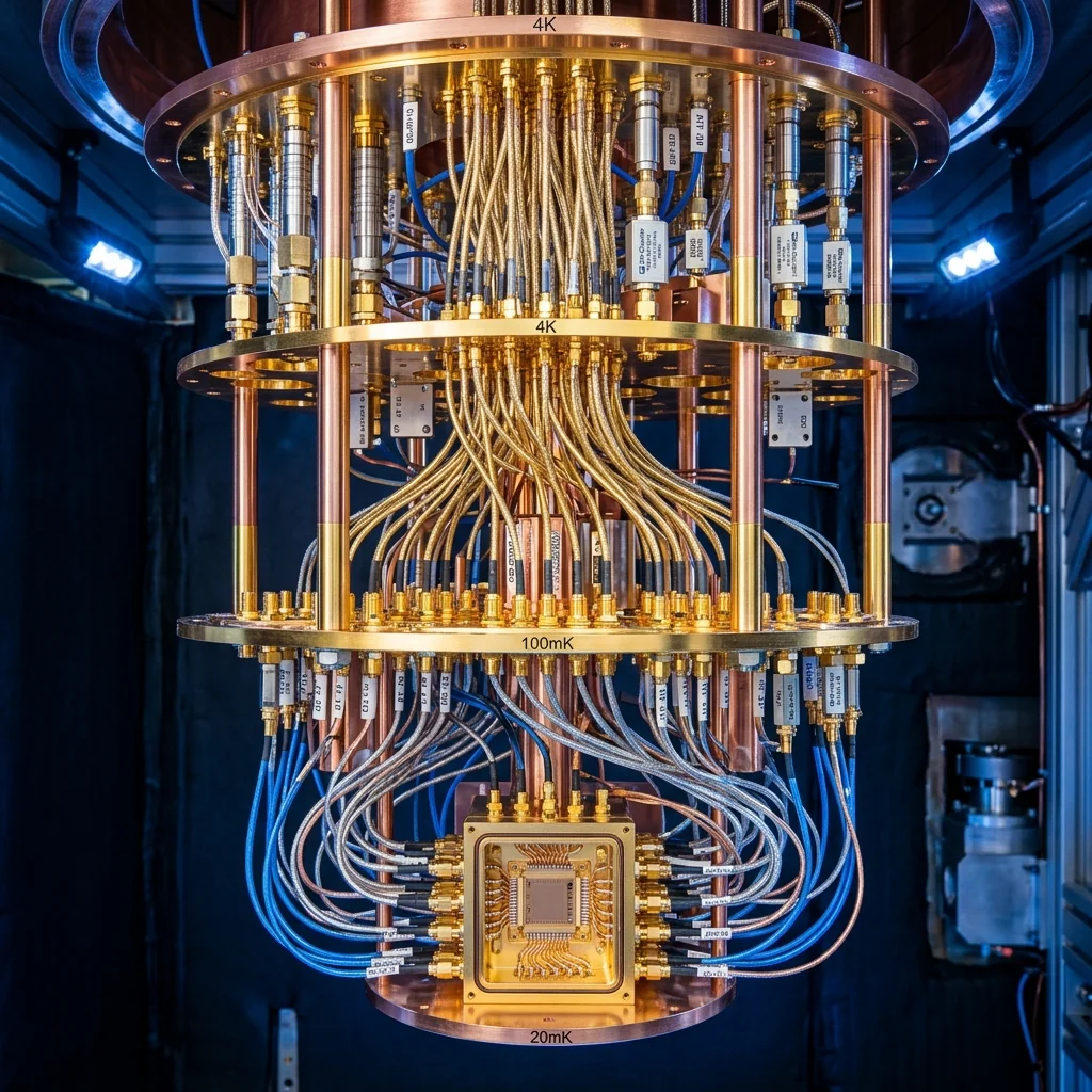
A superconducting qubit stores quantum information in the microwave frequency range, typically between 4 and 8 GHz. Reading the qubit's state without destroying it requires sending a weak microwave probe tone through a coupled resonator, amplifying the reflected or transmitted signal by 80 to 100 dB, and digitizing it at room temperature. The entire readout chain, from the qubit at 15 millikelvin to the digitizer at 300 kelvin, must add less noise than a single microwave photon. This constraint makes the quantum readout chain one of the most demanding RF signal chains ever engineered.
Dispersive Readout: The Operating Principle
Modern superconducting quantum processors use dispersive readout. Each qubit is capacitively coupled to a dedicated readout resonator, a half-wave or quarter-wave coplanar waveguide (CPW) resonator on the same chip. The resonator's frequency shifts by an amount 2χ (the dispersive shift) depending on whether the qubit is in the ground state |0⟩ or the excited state |1⟩. A typical dispersive shift is 1 to 5 MHz.
To read the qubit, the control electronics send a microwave tone at the resonator's frequency. The phase and amplitude of the reflected tone carry the qubit state information. If the qubit is in |0⟩, the resonator is at frequency ω_r + χ. If the qubit is in |1⟩, the resonator is at ω_r - χ. The readout electronics must resolve this frequency shift, which requires a signal-to-noise ratio that can distinguish a few-MHz difference in the resonator response within a measurement window of 200 to 500 nanoseconds.
The Single-Photon Constraint: At the qubit's operating frequency of 5 GHz, the energy of a single microwave photon is hf = 3.3 × 10⁻²⁴ joules, corresponding to a noise temperature of approximately 240 millikelvin. The readout amplifier must add less noise than this single photon, otherwise it would randomize the qubit measurement. This is why quantum-limited amplifiers like Josephson Parametric Amplifiers (JPAs) are essential at the first amplification stage.
The Cryogenic RF Chain
A dilution refrigerator contains multiple thermal stages, each at a progressively lower temperature. The microwave readout chain threads through all of them, with specific components mounted at each stage.
| Temperature Stage | Input Line Components | Output Line Components | Purpose |
|---|---|---|---|
| 300 K (Room Temp) | DAC, upconverter, power control | ADC, downconverter, digital processing | Signal generation and digitization |
| 50 K | Attenuator (10 dB) | HEMT amplifier (35-40 dB gain, 2-4 K NF) | Thermal noise anchoring; first high-gain stage |
| 4 K | Attenuator (20 dB), IR filter | Isolator, bandpass filter | Major attenuation stage; signal conditioning |
| 800 mK | Attenuator (6 dB) | Directional coupler | Fine noise reduction |
| 100 mK | Attenuator (3 dB), low-pass filter | Circulator + JPA or TWPA | Final attenuation; quantum-limited amplification |
| 15 mK (MXC) | Microwave launch to chip | Readout resonator output | Qubit chip connection |
Input Attenuation Strategy
The input line carries the readout probe tone down to the qubit. Even though the tone originates from a clean signal generator, the 300 K thermal noise riding on the cable would overwhelm the qubit if it reached the chip unattenuated. The total input attenuation is typically 50 to 70 dB, distributed across the thermal stages. Each attenuator is thermally anchored to its stage, ensuring that the noise power at its output corresponds to the local temperature rather than the 300 K room temperature.
Precision low-power terminations are used to calibrate the input line attenuation at cryogenic temperatures. The return loss and power handling at millikelvin temperatures must remain stable, which requires careful material selection, particularly avoiding magnetic materials that could distort the qubit's fragile quantum state.
Output Amplification Chain
The output line carries the readout signal from the qubit chip to the room-temperature digitizer. The signal is extraordinarily weak: a few photons at the readout resonator frequency, corresponding to power levels of -130 to -140 dBm. The first amplifier in the chain sets the system noise floor, and it must be quantum-limited.
- Josephson Parametric Amplifier (JPA): mounted at the 100 mK stage. Provides 20 to 25 dB of gain with noise performance at or near the quantum limit (0.5 photons of added noise). Bandwidth is narrow, typically 10 to 50 MHz, which limits the number of readout tones that can be amplified simultaneously.
- Traveling Wave Parametric Amplifier (TWPA): a newer technology that provides 20 dB of gain across 4 to 8 GHz of bandwidth, enabling multiplexed readout of dozens of qubits through a single output line. TWPAs use Josephson junction arrays or kinetic inductance transmission lines pumped at a single frequency.
- HEMT amplifier: mounted at the 4 K stage. A High Electron Mobility Transistor amplifier provides 35 to 40 dB of gain with a noise temperature of 2 to 4 K. While this is far above the quantum limit, it is acceptable as a second-stage amplifier because the first-stage JPA/TWPA has already boosted the signal above the HEMT's noise floor.
Multiplexed Readout: Scaling to Thousands of Qubits
Current quantum processors contain 50 to 1,000 qubits, and each qubit requires a dedicated readout resonator. Running a separate coaxial line for every resonator from 15 mK to 300 K is physically impossible beyond a few hundred qubits: the heat load from the cables would overwhelm the dilution refrigerator's cooling power.
Frequency-division multiplexing solves this by assigning each readout resonator a unique frequency within the 4 to 8 GHz band. A single output line carries all resonator tones simultaneously, and the room-temperature electronics demultiplex them digitally. With resonator spacings of 10 to 20 MHz, a single 4 GHz bandwidth output line can carry 200 to 400 readout channels. This is why broadband TWPAs are critical for scaling: a narrowband JPA cannot amplify all 200 tones at once.
Cable and Connector Selection
The coaxial cables used inside a dilution refrigerator are not standard laboratory cables. Each thermal stage requires a cable with specific thermal conductivity and RF performance trade-offs:
| Stage Transition | Cable Type | Thermal Conductivity | RF Loss at 6 GHz | Purpose |
|---|---|---|---|---|
| 300K to 50K | Stainless steel coax | Very low | High (~3 dB/m) | Minimize heat leak |
| 50K to 4K | Stainless steel coax | Very low | High (~3 dB/m) | Minimize heat leak |
| 4K to MXC (input) | NbTi superconducting coax | Very low | Very low (<0.1 dB/m) | Low loss + low heat |
| 4K to MXC (output) | NbTi superconducting coax | Very low | Very low (<0.1 dB/m) | Preserve signal fidelity |
Connectors at cryogenic temperatures must survive thermal cycling from 300 K to 15 mK without degrading contact resistance or changing impedance. SMA and SMP connectors are standard in current systems. The precision RF connectors and adapters used in quantum systems must be non-magnetic (no nickel plating) and must maintain specified return loss across the full 4 to 8 GHz readout band at operating temperature.
The Room-Temperature Electronics
At 300 K, the readout electronics generate the probe tones (using DACs and IQ modulators), receive the amplified return signals (using IQ demodulators and ADCs), and perform the digital signal processing to extract the qubit state. The key specifications are phase noise of the local oscillator (which limits readout fidelity), ADC sample rate and resolution (typically 1 GS/s, 14 bits), and the latency of the digital processing pipeline (which must complete within the qubit's coherence time of 50 to 300 microseconds for real-time feedback).
Frequently Asked Questions
What makes the superconducting qubit readout chain so demanding?
The chain spans 15 mK at the chip to 300 K at the digitizer and must amplify a signal of only a few photons by 80 to 100 dB while adding less noise than a single microwave photon. At the 5 GHz readout frequency that photon corresponds to a noise temperature of roughly 240 mK. That single-photon budget is why the first amplification stage must be a quantum-limited amplifier rather than a conventional one.
How is the input line attenuated across the refrigerator stages?
The readout tone needs a total of 50 to 70 dB of attenuation distributed across the thermal stages, not applied all at once. Each attenuator is thermally anchored to its stage so that the noise at its output corresponds to the local temperature rather than 300 K. This progressive attenuation strips the room-temperature thermal noise riding on the cable before it can reach and overwhelm the fragile qubit chip.
What amplifiers make up the cryogenic output chain?
A quantum-limited Josephson parametric amplifier or traveling wave parametric amplifier sits near the 100 mK stage as the first stage and sets the system noise floor; a JPA adds about 0.5 photons over a narrow band, while a TWPA gives 20 dB across 4 to 8 GHz for multiplexed readout. A HEMT amplifier at the 4 K stage then adds 35 to 40 dB at a 2 to 4 K noise temperature, which is acceptable because the first stage has already lifted the signal above its floor.