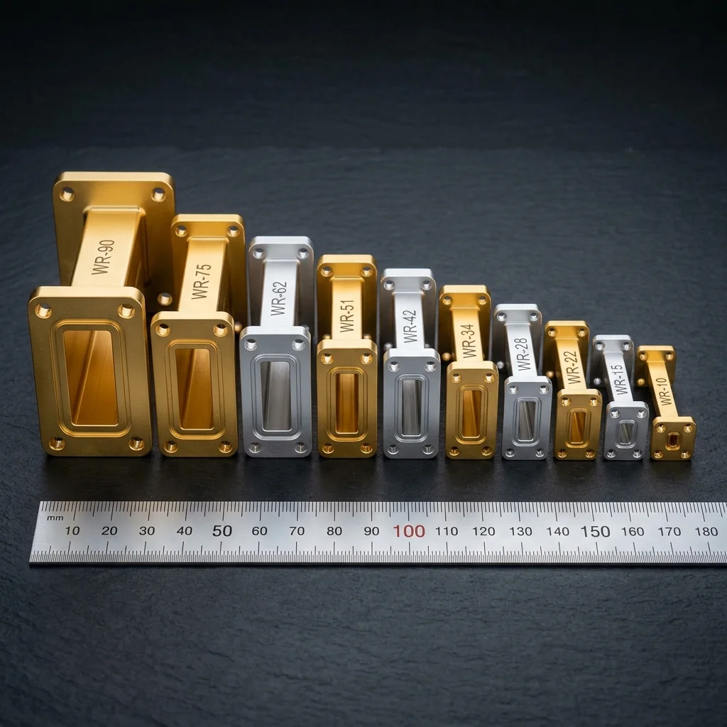
The WR designation system assigns a number to each standard rectangular waveguide size. That number represents the broad wall internal dimension in hundredths of an inch: WR-90 has a broad wall of 0.900 inches (22.86 mm), WR-28 has a broad wall of 0.280 inches (7.112 mm), and WR-03 has a broad wall of 0.034 inches (0.864 mm). Every WR size has a defined single-mode operating band where only the TE₁₀ mode propagates. Selecting the correct WR size for your frequency is the first decision in any waveguide system design, and getting it wrong means either no propagation (below cutoff) or multimode interference (above the next mode's cutoff).
The Complete WR Size Reference
The following table covers the most commonly used WR sizes from L-band through the upper reaches of the millimeter-wave spectrum. RF Essentials manufactures components in every size listed below.
| WR Size | Band | Freq Range (GHz) | Cutoff TE₁₀ (GHz) | Broad Wall (mm) | Atten (dB/m) |
|---|---|---|---|---|---|
| WR-650 | L | 1.12 - 1.70 | 0.908 | 165.10 | 0.004 |
| WR-430 | L/S | 1.70 - 2.60 | 1.372 | 109.22 | 0.007 |
| WR-284 | S | 2.60 - 3.95 | 2.078 | 72.14 | 0.013 |
| WR-187 | C | 3.95 - 5.85 | 3.153 | 47.55 | 0.024 |
| WR-137 | C | 5.85 - 8.20 | 4.301 | 34.85 | 0.040 |
| WR-90 | X | 8.20 - 12.40 | 6.557 | 22.86 | 0.074 |
| WR-62 | Ku | 12.40 - 18.00 | 9.488 | 15.80 | 0.131 |
| WR-42 | K | 18.00 - 26.50 | 14.051 | 10.67 | 0.256 |
| WR-28 | Ka | 26.50 - 40.00 | 21.077 | 7.112 | 0.501 |
| WR-22 | Q | 33.00 - 50.00 | 26.346 | 5.690 | 0.743 |
| WR-19 | U | 40.00 - 60.00 | 31.391 | 4.775 | 1.02 |
| WR-15 | V | 50.00 - 75.00 | 39.875 | 3.759 | 1.51 |
| WR-12 | E | 60.00 - 90.00 | 48.373 | 3.099 | 2.16 |
| WR-10 | W | 75.00 - 110.00 | 59.015 | 2.540 | 3.01 |
| WR-08 | F | 90.00 - 140.00 | 73.768 | 2.032 | 4.40 |
| WR-06 | D | 110.00 - 170.00 | 90.791 | 1.651 | 6.45 |
| WR-05 | G | 140.00 - 220.00 | 115.75 | 1.295 | 9.50 |
| WR-03 | J | 220.00 - 325.00 | 173.57 | 0.864 | 18.0 |
Selection Criteria
Rule 1: Your Frequency Must Fall Within the Operating Band
The operating band of each WR size extends from approximately 1.25× the TE₁₀ cutoff frequency to approximately 1.9× the cutoff frequency. Below the lower limit, the waveguide is near cutoff and attenuation increases sharply. Above the upper limit, the TE₂₀ mode can propagate, creating multimode interference. Always select a WR size where your operating frequency falls comfortably within the defined operating band.
Rule 2: Center-Band Operation Is Best
Waveguide performance is optimal near the center of the operating band. At the band edges, VSWR of components increases, insertion loss rises, and bandwidth of resonant structures (filters, couplers) narrows. If your system operates at 35 GHz, WR-28 (26.5 to 40 GHz) places you near the center of the band. WR-22 (33 to 50 GHz) would also propagate at 35 GHz but would place you near the lower band edge, where performance is worse.
Overlapping Bands: Several WR sizes have overlapping frequency ranges. WR-28 covers 26.5 to 40 GHz and WR-22 covers 33 to 50 GHz. The overlap from 33 to 40 GHz means you could use either size. In the overlap region, choose the larger WR size (WR-28) for lower attenuation and higher power handling, or the smaller WR size (WR-22) for compact packaging. In general, the larger size is preferred unless space constraints dictate otherwise.
Rule 3: Consider Attenuation for Long Runs
Waveguide attenuation increases with frequency. WR-90 at X-band has only 0.074 dB/m, while WR-10 at W-band has 3.01 dB/m. For a 2-meter waveguide run, that is 0.15 dB at X-band versus 6 dB at W-band. At millimeter-wave frequencies, every unnecessary inch of waveguide costs measurable signal. Keep runs as short as possible and use precision bends to route around obstacles rather than adding length with straight sections.
Rule 4: Power Handling Scales with Size
The power handling capacity of a waveguide is limited by the peak electric field at atmospheric breakdown. Larger WR sizes handle more power because the electric field is distributed over a larger cross-section. WR-90 can handle approximately 250 kW peak and 2 kW CW at standard conditions. WR-10 handles only about 5 kW peak and 50 W CW. For high-power applications (radar transmitters, particle accelerators), the WR size may be determined by power handling rather than frequency.
Flange and Interface Standards
Every WR size has associated flange standards that define the bolt pattern, alignment features, and mating surfaces. Common flange types include:
- UG (United Government): the original military standard flanges. Cover (flat face) and choke (grooved face) pairs. Widely available and inexpensive. Used with rubber gaskets for pressurized systems.
- CPR (Connector, Pressurizable, Rectangular): precision flanges with alignment pins for repeatable connections. Standard for test equipment and precision assemblies. Available in CPR-90, CPR-62, CPR-42, CPR-28, and smaller sizes.
- CMR (Connector, Miniature, Rectangular): compact flanges for space-constrained applications. Smaller bolt circle than CPR. Common in millimeter-wave test setups where physical space is limited.
When ordering waveguide components, always specify the flange type along with the WR size. A WR-28 bend with UG-599/U flanges will not mate directly with a WR-28 adapter that has CPR-28G flanges without a flange adapter.
Quick Selection Flowchart
- Determine your operating frequency range.
- Identify all WR sizes whose operating band includes your frequency.
- If only one WR size fits, select it.
- If multiple sizes overlap, choose the one that places your frequency nearest band center.
- Verify that the selected size meets your power handling requirements.
- Verify that component availability (bends, couplers, filters, adapters) exists for your chosen WR size and flange type.
- Specify the flange standard and order.
RF Essentials stocks and manufactures waveguide components in every standard WR size from WR-650 through WR-03. Every product is CNC machined in the USA with tolerances specified for your frequency band. Need help selecting the right WR size? Our engineering team is standing by.
Frequently Asked Questions
How do I choose the right WR size for my operating frequency?
Each WR size has a single-mode band running from roughly 1.25 times its TE10 cutoff to about 1.9 times cutoff, and performance is best near band center. For 35 GHz, WR-28 at 26.5 to 40 GHz puts you near center, whereas WR-22 would also propagate but place you at its lower edge with worse VSWR and loss. When bands overlap, the larger size gives lower attenuation and higher power handling.
What happens if I operate a waveguide outside its single-mode band?
Below the lower band limit the guide is near cutoff, so attenuation rises sharply and very little power propagates. Above the upper limit the next mode, TE20, begins to propagate alongside TE10, creating multimode interference that corrupts amplitude and phase. Staying within the defined operating band is what keeps a waveguide single-mode and predictable, which is why size selection is the first design decision.
How much does waveguide attenuation matter at millimeter-wave frequencies?
Attenuation climbs steeply with frequency. WR-90 at X-band loses only 0.074 dB per meter, but WR-10 at W-band loses 3.01 dB per meter. Over a 2 meter run that is 0.15 dB at X-band versus a punishing 6 dB at W-band. At millimeter-wave frequencies every unnecessary inch costs measurable signal, so keep runs short and use precision bends to route around obstacles rather than adding straight length.