Waveguide flanges should be the simplest part of a waveguide system. Two flat metal surfaces, four bolts, and an alignment mechanism. In practice, flange selection and compatibility cause more procurement delays, integration headaches, and field failures than almost any other passive component. The reason is simple: there are too many flange standards, too many legacy designations, and too few clear references explaining which flanges mate with which.
This application note is that reference. It covers every flange family you will encounter, explains the compatibility rules, and provides the quick-reference tables that should be pinned above every RF engineer's desk.
1. Flange Families
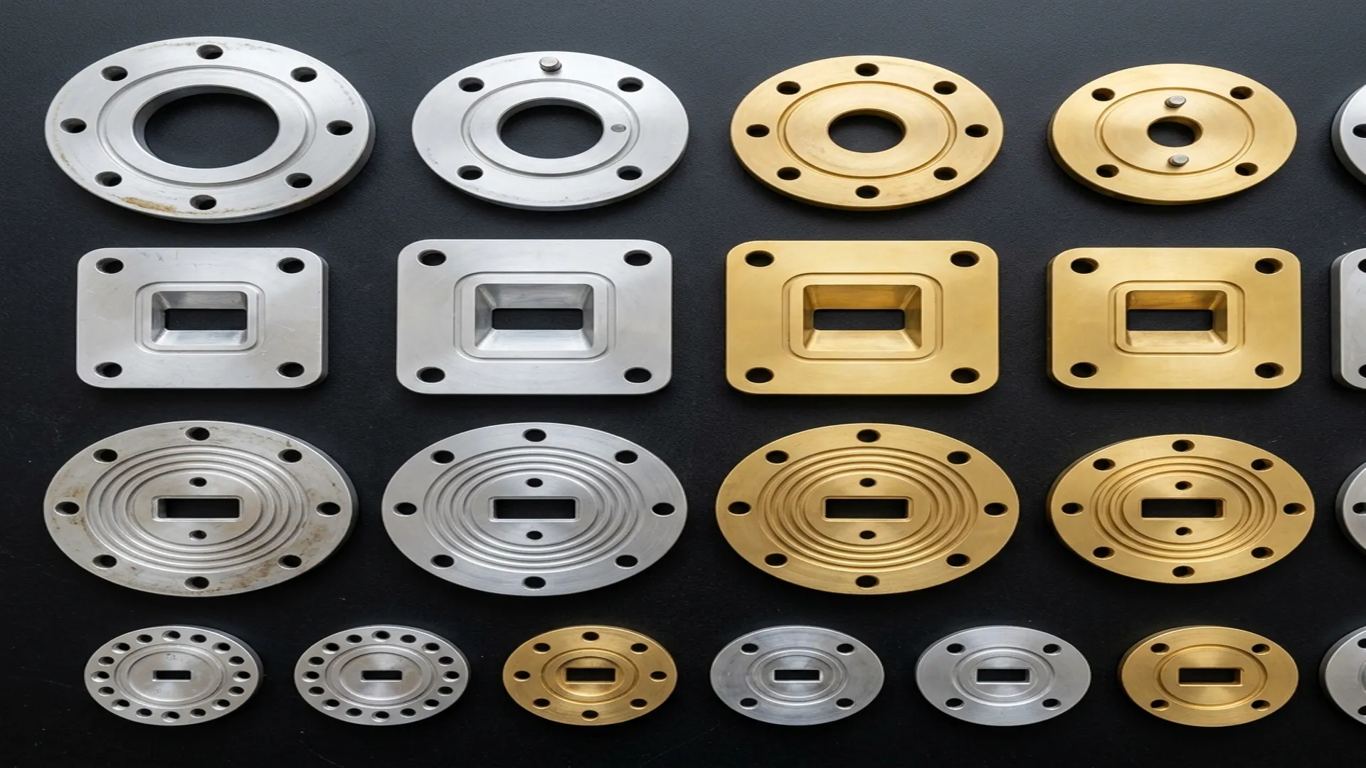
UG-Style Round Flanges (MIL-DTL-3922)
The original military-standard waveguide flange. Identified by a UG designation number (e.g., UG-39/U for WR-284, UG-135/U for WR-90). Features a circular flange body with four bolt holes on a circular pattern. UG flanges come in two variants:
- Cover (flat face): A flat mating surface with alignment pins. The simplest and most common configuration.
- Choke (grooved face): A concentric groove machined into the mating surface that creates a non-contacting RF seal. The choke groove acts as a quarter-wave transformer that presents a short circuit at the flange joint, forcing the RF current to flow through the waveguide walls rather than across the flange interface.
Cover + Choke Pairing: The correct pairing is always one cover flange mated with one choke flange. A cover-to-cover joint works but has higher VSWR because the RF current must flow across the physical metal-to-metal contact. A choke-to-choke joint should never be used because the two choke grooves interact unpredictably, creating resonant behavior at certain frequencies.
CPR Flanges (IEC 60154)
The "Contact, Pressurizable, Rectangular" flange is the modern international standard for waveguide connections. CPR flanges feature a square or rectangular flange body, a flat mating surface with an O-ring groove for pressurization, and precision alignment pins. They are identified by a CPR number that corresponds to the waveguide size (e.g., CPR-284 for WR-284, CPR-90 for WR-90).
CMR Flanges
The "Connector, Miniature, Rectangular" flange is a compact variant used at higher frequencies (Ka-band and above) where the UG-style round flange is too large relative to the waveguide aperture. CMR flanges use a smaller bolt pattern and precision dowel pins for alignment.
Square Cover Flanges (PDR/EIA)
Square cover flanges used primarily in commercial applications. A flat square flange with four bolt holes at the corners. Simple, inexpensive to manufacture, and adequate for applications where pressurization is not required.
2. Quick Reference: Standard Flanges by Waveguide Size
| Waveguide | Band | UG Cover | UG Choke | CPR | Square Cover |
|---|---|---|---|---|---|
| WR-284 | S | UG-53/U | UG-54/U | CPR-284G | PDR-284 |
| WR-187 | C | UG-407/U | UG-406/U | CPR-187G | PDR-187 |
| WR-137 | C | UG-344/U | UG-343/U | CPR-137G | PDR-137 |
| WR-112 | X | UG-51/U | UG-52/U | CPR-112G | PDR-112 |
| WR-90 | X | UG-135/U | UG-136/U | CPR-90G | PDR-90 |
| WR-62 | Ku | UG-419/U | UG-541/U | CPR-62G | PDR-62 |
| WR-42 | K | UG-595/U | UG-596/U | CPR-42G | PDR-42 |
| WR-28 | Ka | UG-599/U | UG-600/U | CPR-28G | PDR-28 |
| WR-22 | Q | UG-383/U | UG-384/U | CMR-22 | - |
| WR-15 | V | UG-385/U | UG-386/U | CMR-15 | - |
| WR-10 | W | UG-387/U | UG-388/U | CMR-10 | - |
3. Compatibility Rules
- Same waveguide size is mandatory. A WR-90 flange will not mate with a WR-62 flange. The aperture dimensions are different.
- Same flange family is strongly recommended. A UG-135/U (WR-90 cover) mates cleanly with a UG-136/U (WR-90 choke). Mixing UG and CPR flanges of the same waveguide size requires an adapter.
- Cover + choke is the preferred pairing. This gives the lowest VSWR at the joint. Cover + cover works but with degraded performance. Choke + choke should never be used.
- Alignment pins must match. If one flange has alignment pins, the mating flange must have corresponding holes. Misaligned flanges cause waveguide aperture mismatch and elevated VSWR.
- Bolt patterns must match. Different flange families use different bolt hole patterns, thread sizes, and bolt circle diameters. Always verify mechanical compatibility before ordering.
4. When to Use Pressurizable Flanges
Pressurizable flanges (CPR-style with O-ring grooves) are required when the waveguide system is pressurized with dry nitrogen or dry air to prevent moisture ingress. This is standard practice for:
- Outdoor antenna feed systems exposed to weather
- Shipboard and military systems in salt-spray environments
- High-altitude applications where reduced air pressure affects power handling
- Any system where condensation inside the waveguide would cause arcing or signal degradation
RF Essentials provides complete flange dimension tables for every standard waveguide size, including cover, choke, pressurizable, square, and round-contact variants.
Frequently Asked Questions
What is the difference between cover, choke, and CPR waveguide flanges?
A UG cover flange has a flat mating face with alignment pins, while a UG choke flange adds a quarter-wave groove that forms a non-contacting RF short for lower-loss joints. CPR flanges are the modern international standard, with a rectangular body and an O-ring groove for pressurization. CMR flanges are a compact variant for Ka-band and above, where a round UG flange would be oversized relative to the small aperture.
Can I mate flanges from different families or waveguide sizes?
Size must match exactly: a WR-90 flange will not mate with a WR-62 flange because the apertures differ. Family matters too. A UG cover mates cleanly with the matching UG choke, but mixing UG and CPR flanges of the same size requires an adapter because the bolt patterns, thread sizes, and bolt-circle diameters differ. Always verify both the aperture and the mechanical bolt pattern before ordering.
When do I need pressurizable flanges?
Pressurizable CPR-style flanges with O-ring grooves are required whenever the system is filled with dry nitrogen or dry air to keep moisture out. That covers outdoor antenna feeds exposed to weather, shipboard and military systems in salt-spray environments, high-altitude installations where reduced pressure affects power handling, and any run where internal condensation could cause arcing or signal degradation.