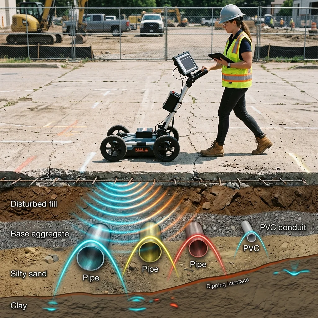
Most radar systems point their antennas at the sky or across the horizon. Ground-penetrating radar (GPR) points downward, sending electromagnetic pulses into soil, concrete, rock, and ice to image structures that are invisible from the surface. The applications range from locating buried utilities before excavation, to detecting unexploded ordnance, to mapping geological strata for civil engineering, to archaeological surveys that reveal ancient structures without disturbing a single grain of sand. The RF engineering challenge is fundamentally different from airborne or marine radar: the propagation medium is not air with its predictable 3 dB per doubling-of-distance behavior, but a lossy dielectric whose properties vary with composition, moisture content, and temperature.
Why GPR Operates Below 3 GHz
Electromagnetic waves attenuate rapidly in soil. The attenuation rate depends on the conductivity of the medium and increases with frequency. Dry sand attenuates signals at roughly 0.01 dB/cm at 100 MHz but 1 dB/cm at 2 GHz. Wet clay, the worst case for GPR penetration, can exceed 10 dB/cm at 1 GHz, limiting usable depth to centimeters. This frequency-dependent attenuation forces GPR designers to operate at low frequencies for deep penetration and accept coarser range resolution as a consequence.
The fundamental trade-off is straightforward: lower frequencies penetrate deeper but resolve less detail. A 100 MHz GPR system can image structures 10 to 30 meters deep in dry sand but cannot resolve features smaller than approximately 50 cm. A 2 GHz system resolves features as small as 2 to 3 cm but penetrates only 30 to 50 cm in typical soil. Most commercial GPR systems operate in the 200 MHz to 2 GHz range, covering the practical sweet spot between depth and resolution for infrastructure, geotechnical, and forensic applications.
| Center Frequency | Typical Depth (dry soil) | Depth (wet soil) | Range Resolution | Primary Application |
|---|---|---|---|---|
| 50 to 100 MHz | 15 to 30 m | 2 to 5 m | 30 to 50 cm | Geological mapping, ice thickness |
| 200 to 400 MHz | 3 to 10 m | 0.5 to 2 m | 10 to 25 cm | Utility location, archaeology |
| 800 MHz to 1 GHz | 1 to 3 m | 0.2 to 0.5 m | 5 to 10 cm | Concrete inspection, rebar mapping |
| 1.5 to 2.6 GHz | 0.3 to 1 m | 0.05 to 0.2 m | 2 to 5 cm | Road surface, bridge deck inspection |
GPR Antenna Design
GPR antennas face unique constraints. They must radiate efficiently at low frequencies (where wavelengths are 30 cm to 3 meters), maintain a broad bandwidth to support the short-duration pulses needed for range resolution, and fit within a portable housing that can be dragged or rolled across uneven terrain. Three antenna types dominate commercial GPR.
Bowtie dipoles are the most common GPR antenna, consisting of two triangular conducting elements fed at the center. The bowtie geometry provides broader bandwidth than a straight dipole (typically 2:1 to 3:1 bandwidth ratio) while maintaining a simple, planar construction. Resistive loading, where the conductors taper into resistive material at the outer edges, further broadens the bandwidth and suppresses late-time ringing at the expense of radiation efficiency. A loaded bowtie at 400 MHz might be 30 cm across and 3 cm thick, small enough for handheld operation.
Vivaldi antennas provide even wider bandwidth (up to 10:1 ratio) through their exponentially tapered slot geometry. Our team at RF Essentials has observed growing adoption of Vivaldi elements in multi-channel GPR arrays where the wider bandwidth enables a single antenna to cover the 200 MHz to 2 GHz range that previously required multiple fixed-frequency antennas.
Horn antennas, particularly TEM (transverse electromagnetic) horns, offer the highest gain and best-defined radiation patterns for GPR. A TEM horn at 500 MHz might be 40 cm long and 30 cm wide, producing 8 to 12 dBi of gain with a well-controlled footprint. However, their size makes them unsuitable for handheld operation; they are typically vehicle-mounted for road survey applications.
Pulse Generation and Waveform Design
Traditional GPR systems use impulse waveforms: short-duration pulses (0.5 to 10 ns duration) with bandwidth inversely proportional to pulse width. A 1 ns pulse has a 3 dB bandwidth of approximately 1 GHz, centered around whatever frequency the antenna radiates most efficiently. The impulse approach is simple and requires no receiver correlation, but the peak transmit power is limited by the pulse generator (typically 10 to 100 V into 50 ohms, producing 2 to 200 W peak power) and the average power is very low (microwatts to milliwatts) due to the extremely low duty cycle.
GPR Range Resolution Formula: ΔR = c / (2 × BW × √εr), where c = speed of light, BW = signal bandwidth, εr = relative permittivity of the medium. In air (εr = 1), a 500 MHz bandwidth yields ΔR = 30 cm. In dry sand (εr = 4), the same bandwidth yields ΔR = 15 cm. In wet soil (εr = 16), ΔR = 7.5 cm. Higher permittivity improves resolution because the wavelength shortens in the medium, but attenuation also increases with moisture, creating a natural balance.
Stepped-frequency continuous wave (SFCW) GPR replaces the impulse with a series of single-frequency CW tones that step across the desired bandwidth. The receiver measures amplitude and phase at each frequency, and an inverse FFT converts the frequency-domain data to a time-domain reflection profile equivalent to the impulse response. SFCW systems achieve higher average power (and therefore greater dynamic range) than impulse systems, with 80 to 100 dB of dynamic range compared to 40 to 60 dB for impulse GPR. The penalty is slower data acquisition speed, since each frequency step requires a settling time of 1 to 10 microseconds.
FMCW (frequency-modulated continuous wave) GPR sweeps a continuous chirp across the bandwidth, combining the dynamic range advantages of CW with faster acquisition than stepped frequency. FMCW GPR has become increasingly popular for vehicle-mounted road survey systems, where the survey speed (60 to 100 km/hr) demands rapid data acquisition. The beat frequency after mixing the transmitted and received chirps is proportional to the target depth, with beat frequencies typically in the 1 to 100 kHz range that can be digitized with inexpensive ADCs.
Soil Dielectric Properties and Their Impact
The electromagnetic properties of soil determine everything about GPR performance: propagation velocity (which controls depth calibration), attenuation (which limits maximum depth), and impedance contrast at interfaces (which determines reflection strength). Two parameters dominate: relative permittivity (εr) and conductivity (σ).
Permittivity controls propagation velocity: v = c / √εr. Dry sand has εr of 3 to 5, giving a propagation velocity of 0.13 to 0.17 m/ns. Wet clay has εr of 15 to 40, slowing the wave to 0.05 to 0.08 m/ns. Water itself has εr = 81 at DC (dropping to about 40 at 1 GHz due to the Debye relaxation), which is why moisture content so dramatically affects GPR performance. A 5% increase in volumetric water content can increase εr from 5 to 12, more than doubling the attenuation rate.
Conductivity creates ohmic losses that convert electromagnetic energy to heat. Saline soils, clays with high cation exchange capacity, and contaminated ground all exhibit elevated conductivity. At 500 MHz, a conductivity increase from 1 mS/m (dry sand) to 100 mS/m (wet clay) increases the attenuation from 0.1 dB/m to 15 dB/m, reducing the usable depth from 30 meters to less than 2 meters. This is why GPR works spectacularly well in deserts, glaciers, and dry rocky terrain, but struggles in agricultural soils and coastal regions.
Signal Processing for Subsurface Imaging
Raw GPR data is a 2D image called a B-scan: horizontal axis is antenna position along the survey line, vertical axis is two-way travel time (proportional to depth). Point reflectors appear as hyperbolic curves because the antenna receives energy from off-axis positions before and after passing directly over the target. Converting B-scan data to a focused image requires migration processing, which collapses the hyperbolas to their apexes using knowledge of the propagation velocity.
Background subtraction removes the direct coupling between transmit and receive antennas, which produces a strong, constant signal that obscures shallow reflections. By averaging several hundred traces and subtracting the mean, the stationary direct coupling is removed while the spatially varying subsurface reflections are preserved. This technique requires that the antenna moves at least half a wavelength between successive traces, which at 400 MHz in soil (λ = 19 cm) means a minimum spatial sampling interval of about 10 cm.
Gain compensation applies time-varying gain to counteract the exponential attenuation of the signal with depth. Without compensation, a target at 5 meters depth in dry sand would appear 50 dB weaker than the same target at 0.5 meters. Automatic gain control or SEC (spreading and exponential compensation) functions normalize the amplitude, allowing targets at all depths to be visualized on the same display scale. This processing must be calibrated to the specific soil conditions at each site, and precision RF terminations are used during system calibration to establish the reference noise floor against which gain settings are optimized.
Regulatory and Spectral Considerations
GPR systems in the United States operate under FCC Part 15, Subpart F (Ultra-Wideband devices), which permits unlicensed operation provided the system meets specific emission limits and is operated by qualified users. The FCC defines GPR as an imaging system that must be operated with the antenna in contact with or within 10 cm of the ground surface. This ground-coupling requirement is not just regulatory; it is physically advantageous, as the ground contact improves antenna efficiency and eliminates the air-ground interface reflection that would otherwise mask shallow targets.
The spectral emission limits for GPR under Part 15.509 restrict the average EIRP to -41.3 dBm/MHz above 960 MHz, with additional limits in specific protected bands. For impulse GPR systems with bandwidths spanning 100 MHz to 3 GHz, meeting these limits requires careful pulse shaping and, in some cases, notch filtering to protect GPS (1.575 GHz) and cellular bands. SFCW and FMCW systems have an advantage here because their narrower instantaneous bandwidth allows higher spectral density within the emission mask.
The RF design of a GPR system, from antenna to pulse generator to receiver, is constrained by physics at both ends: the dielectric properties of the ground determine what frequencies will penetrate, and the emission regulations determine how much power can be radiated. Within those constraints, the engineer's task is to maximize dynamic range, optimize the depth-resolution trade-off for the target application, and deliver a system robust enough to operate on muddy construction sites and frozen tundra alike.
RF Essentials manufactures precision waveguide and coaxial components for radar test and calibration: terminations, attenuators, directional couplers, and adapters across all standard waveguide bands. Built in the USA for defense and commercial radar applications.
Frequently Asked Questions
Why does ground-penetrating radar operate below 3 GHz?
Soil attenuates electromagnetic waves rapidly, and the rate climbs with frequency. Dry sand loses about 0.01 dB per centimeter at 100 MHz but 1 dB per centimeter at 2 GHz, and wet clay can exceed 10 dB per centimeter at 1 GHz, limiting depth to centimeters. Low frequencies penetrate deep but resolve coarsely, so most commercial GPR runs between 200 MHz and 2 GHz to balance depth against detail.
What is the depth-versus-resolution trade-off in GPR?
Lower frequencies penetrate deeper but resolve less. A 100 MHz system images 10 to 30 meters deep in dry sand yet cannot resolve features smaller than about 50 cm, while a 2 GHz system resolves 2 to 3 cm but reaches only 30 to 50 cm in typical soil. Resolution follows delta R equals c over twice the bandwidth times the square root of permittivity, so higher permittivity shortens the wavelength and sharpens resolution even as moisture raises attenuation.
What antenna types are used in ground-penetrating radar?
Three dominate. Bowtie dipoles are the most common, broadband and planar, often resistively loaded at the edges to suppress late-time ringing. Vivaldi tapered-slot antennas reach up to a 10 to 1 bandwidth ratio, so a single element can cover 200 MHz to 2 GHz in a multi-channel array. TEM horns give the highest gain and the best-defined pattern but are large, so they are typically vehicle-mounted for road and bridge-deck surveys.