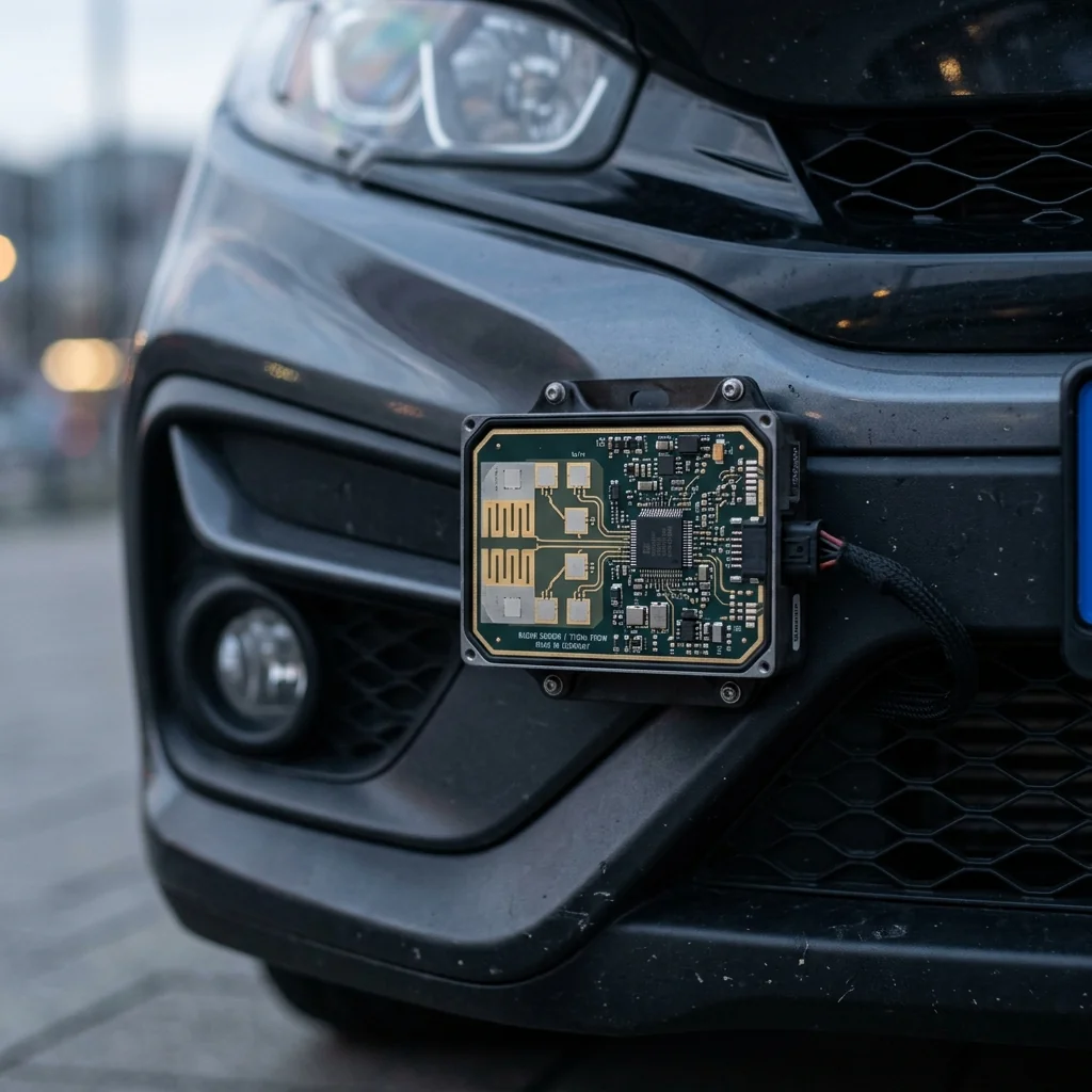
Frequency Modulated Continuous Wave (FMCW) radar transmits continuously, unlike pulsed radar which transmits in bursts. A linear frequency sweep, or chirp, is transmitted and the echo from a target is mixed with the ongoing transmit signal. The resulting "beat frequency" is directly proportional to the target's range. If the target is moving, the beat frequency also contains a Doppler shift proportional to the target's radial velocity. By processing sequences of chirps, an FMCW radar can simultaneously measure the range, velocity, and angle of multiple targets. This principle underlies every automotive radar on the road today, every industrial level sensor on a factory floor, and an increasing number of defense and security systems.
The Beat Frequency: Range Measurement
An FMCW radar transmits a chirp that sweeps linearly from frequency f₀ to f₀ + B over a duration T_chirp. The chirp rate is S = B/T_chirp (Hz/s). The echo from a target at range R arrives with a time delay τ = 2R/c. During this delay, the transmitter's frequency has advanced by f_beat = S × τ = (2 × S × R) / c. This beat frequency is extracted by mixing the received echo with a copy of the transmitted chirp.
The range is then R = (f_beat × c) / (2S) = (f_beat × c × T_chirp) / (2B). The range resolution is determined by the chirp bandwidth: ΔR = c / (2B). A 4 GHz bandwidth chirp (common in automotive radar at 77 GHz) achieves a range resolution of 3.75 cm.
| Parameter | Short-Range (24 GHz) | Long-Range (77 GHz) | Imaging (94 GHz) | Industrial (60 GHz) |
|---|---|---|---|---|
| Bandwidth | 200 MHz | 1-4 GHz | 500 MHz - 2 GHz | 500 MHz |
| Range resolution | 75 cm | 3.75-15 cm | 7.5-30 cm | 30 cm |
| Max range | 30 m | 200-300 m | 50-100 m | 15-100 m |
| Chirp duration | 50-100 μs | 10-60 μs | 20-100 μs | 100-500 μs |
| IF bandwidth | 1-5 MHz | 5-40 MHz | 2-20 MHz | 1-10 MHz |
Worked Example: A 77 GHz automotive radar with B = 4 GHz bandwidth and T_chirp = 40 μs has a chirp rate S = 100 MHz/μs. A target at 50 meters produces a beat frequency of f_beat = (2 × 100 × 10⁶ × 50) / (3 × 10⁸) = 33.3 kHz. A target at 200 meters produces f_beat = 133.3 kHz. The IF filter and ADC need only process signals in the 0 to 200 kHz range, not the full 77 GHz carrier frequency. This is the fundamental advantage of FMCW: it converts a wideband radar problem into a narrowband signal processing problem.
Velocity Measurement: The Doppler Dimension
A single chirp measures range but cannot distinguish between range and velocity. A moving target shifts the beat frequency by the Doppler frequency f_D = (2 × v × f₀) / c, where v is the radial velocity and f₀ is the carrier frequency. At 77 GHz, a target moving at 30 m/s (108 km/h) produces f_D = 15.4 kHz. This Doppler shift adds to (or subtracts from) the range beat frequency, causing a range measurement error.
The solution is to transmit a frame of N chirps (typically 64 to 256) and perform a two-dimensional FFT. The first FFT (across samples within each chirp) extracts the beat frequency, which maps to range. The second FFT (across the same range bin of successive chirps) extracts the Doppler frequency, which maps to velocity. The result is a range-Doppler map: a 2D matrix where each cell contains the signal power at a specific range and velocity combination.
The Range-Doppler Map
Each target appears as a peak in the range-Doppler map. The range axis has N_samples bins (determined by the ADC sample rate and chirp duration), and the Doppler axis has N_chirps bins. The maximum unambiguous velocity is v_max = λ / (4 × T_chirp), where λ is the wavelength and T_chirp is the chirp repetition interval. At 77 GHz with T_chirp = 50 μs, v_max = 19.5 m/s (70 km/h). Shorter chirps extend the unambiguous velocity range but reduce the maximum detectable range.
The RF Front End
An FMCW radar's RF front end is simpler than a pulsed radar's because there is no high-power transmit/receive switch and no need for a high-peak-power amplifier. The key components are:
- Voltage-controlled oscillator (VCO) or PLL synthesizer: generates the chirp. Modern 77 GHz radars use integrated PLL-VCO combinations that sweep 4 GHz in 40 μs with linearity errors below 0.1%.
- Power amplifier: at 77 GHz, integrated SiGe or CMOS PAs produce 10 to 13 dBm of output power. This is far below the kilowatt levels of pulsed radar, but sufficient for ranges up to 300 meters with the processing gain from coherent integration.
- Low-noise amplifier (LNA): the receiver LNA must maintain a low noise figure (4 to 7 dB at 77 GHz) across the full chirp bandwidth. Any gain variation across the chirp bandwidth creates ghost targets in the range profile.
- Mixer: mixes the received echo with the transmitted chirp to produce the IF beat signal. The mixer must maintain low conversion loss and high LO-to-RF isolation to prevent transmitter leakage from saturating the IF chain.
For laboratory characterization of FMCW radar modules, the waveguide components used in the test setup must maintain calibrated performance across the full chirp bandwidth. A precision waveguide termination provides the matched load reference, while directional couplers sample the transmitted and received signals for power monitoring.
Signal Processing Pipeline
- Windowing: apply a Hanning or Blackman window to each chirp's IF data before the range FFT to suppress range sidelobes.
- Range FFT: N-point FFT of each chirp's sampled data. Produces a range profile with N/2 range bins.
- Doppler FFT: M-point FFT across the same range bin of M chirps. Produces M Doppler bins per range bin.
- CFAR detection: Constant False Alarm Rate detector scans the range-Doppler map and identifies cells that exceed a threshold set by the local noise level.
- Angle estimation: for multi-channel receivers (MIMO or phased array), a third FFT or beamforming operation across the receive channels provides angle-of-arrival information.
- Clustering and tracking: detected points are grouped into objects and tracked across frames using Kalman filtering or similar algorithms.
Precision waveguide terminations, couplers, and calibration standards for FMCW radar development and testing. WR-12, WR-10, and WR-15 sizes for 60 GHz, 77 GHz, and 94 GHz systems.
Frequently Asked Questions
How does FMCW radar measure range?
An FMCW radar transmits a linear frequency chirp and mixes the returning echo with the ongoing transmit signal. The target's round-trip delay produces a beat frequency directly proportional to its range. Range resolution depends only on the chirp bandwidth, where delta R equals c over 2B, so a 4 GHz chirp at 77 GHz resolves about 3.75 cm. This turns a wideband radar problem into narrowband signal processing, since the beat is only tens to hundreds of kilohertz.
How does FMCW radar measure velocity?
A single chirp cannot separate range from velocity, so the radar transmits a frame of 64 to 256 chirps and runs a two-dimensional FFT. The first FFT, across the samples within each chirp, extracts the beat frequency that maps to range. The second FFT, across the same range bin of successive chirps, extracts the Doppler shift that maps to radial velocity. The result is a range-Doppler map in which each target appears as a distinct peak.
Why is the FMCW front end simpler than a pulsed radar's?
There is no high-power transmit/receive switch and no high-peak-power amplifier. The key parts are a PLL-VCO synthesizer that sweeps the 4 GHz chirp in about 40 microseconds with under 0.1 percent linearity, a modest 10 to 13 dBm SiGe or CMOS power amplifier at 77 GHz, an LNA that holds a 4 to 7 dB noise figure flat across the chirp to avoid ghost targets, and a mixer with high LO-to-RF isolation so transmit leakage does not saturate the IF chain.