Forget everything you know about copper. For over a century, RF engineering has been a slave to the antenna theory rulebook: if you want to intercept a wave, you need a piece of metal cut to a specific fraction of that wave's length (L = λ/4 or λ/2). The antenna's physical dimensions dictate its operating frequency, its bandwidth, and its gain. This is the foundation of every receiver ever built.
But what if you could build an antenna that had no physical size constraint? What if your "antenna" was a cloud of atoms that could sense every frequency from DC to terahertz simultaneously? That is the promise of Rydberg atom antennas. It is not an incremental upgrade to existing technology. It is a complete rewrite of the RF signal chain from the ground up.
1. The Physics: What Is a Rydberg Atom?
In a normal atom, electrons occupy low-energy orbitals close to the nucleus. A Rydberg atom is an atom (usually an alkali metal like Rubidium-85 or Cesium-133) that has been pumped with laser energy until its outermost electron is pushed into an extremely high principal quantum number state, occupying a massive, diffuse orbital.
To put this in perspective: if the nucleus were the size of Earth, a normal ground-state electron would be a plane flying at 30,000 feet. In a Rydberg atom at n = 50, that electron is orbiting halfway to the Moon.
Why This Matters for RF
Because that outermost electron is so far from the nucleus, it is barely bound. The atom becomes extraordinarily polarizable, meaning even the tiniest external electric field can perturb its quantum state. A Rydberg atom is, in effect, a sub-atomic antenna element with a sensitivity that scales with the principal quantum number.
Key Concepts
- Principal Quantum Number (n): This defines the orbital energy level. For Rydberg antenna applications, atoms are typically pumped to n > 40. The sensitivity of the atom to external electric fields scales as n7. Moving from n = 30 to n = 50 increases sensitivity by roughly two orders of magnitude.
- Electromagnetically Induced Transparency (EIT): This is the readout mechanism. Two precisely tuned lasers interact with the atom vapor to create a narrow transparency window in the optical absorption spectrum. When an external RF field hits the atoms, it shifts the energy levels (via Autler-Townes splitting), which breaks the transparency. By monitoring the transmitted laser power with a photodetector, the system "sees" the RF field as a change in optical intensity.
- Autler-Townes Splitting: When the RF field is strong enough, it splits the EIT transparency peak into two distinct peaks. The separation between these peaks is directly proportional to the RF electric field amplitude, providing a self-calibrating measurement that traces directly to Planck's constant. No external calibration standard is required.
Fundamental Advantage: A conventional antenna measures voltage or current induced in a conductor. A Rydberg sensor measures the electric field directly at the atomic level, referenced to a fundamental physical constant. This makes it an intrinsic SI-traceable sensor, something no classical antenna can claim.
2. The Architecture: How the "Antenna" Works
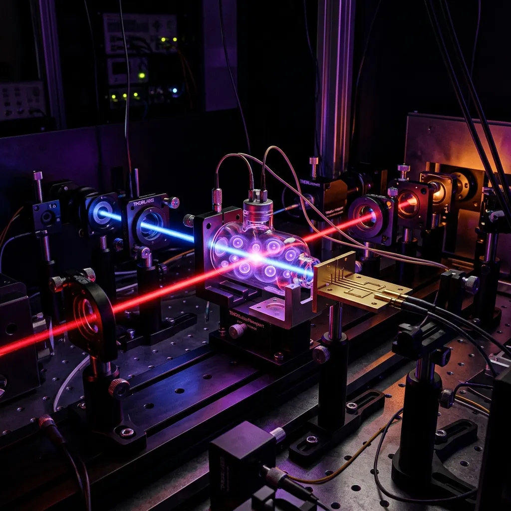
A Rydberg antenna does not look like a Yagi, a patch, or a horn. It looks like a small glass cell with laser beams passing through it. There are no wires, no RF connectors, and no metal in the sensing element.
The Signal Chain
- The Vapor Cell: A small sealed glass ampoule (typically 10-50 mm in length) containing a low-pressure gas of Rubidium or Cesium atoms at room temperature or slightly above.
- The Probe Laser (~780 nm for Rb): A weak laser beam passes through the vapor. It is tuned to the D2 transition of Rubidium (5S₁/₂ → 5P₃/₂), which the atoms normally absorb.
- The Coupling Laser (~480 nm for Rb): A second, counter-propagating laser beam is tuned to drive the atoms from the 5P₃/₂ state to a high-lying Rydberg state (e.g., nS or nD). The combination of both lasers creates the EIT condition, making the vapor transparent to the probe laser at a specific frequency.
- The RF Interaction: An external RF signal passes through the glass cell. If its frequency matches a transition between two Rydberg states, it perturbs the atomic energy levels, disrupting the EIT transparency.
- Optical Readout: A photodetector at the end of the probe laser path measures the change in transmitted light. This optical signal is converted to an electrical output, effectively transducing the RF field into a measurable voltage.
| Parameter | Classical Antenna | Rydberg Atom Sensor |
|---|---|---|
| Sensing Element | Metal conductor (copper, aluminum) | Atomic vapor (Rb, Cs) in glass cell |
| Size Constraint | Must be ~λ/4 or λ/2 for resonance | Sub-wavelength at all frequencies |
| Frequency Range | Narrowband, fixed by geometry | DC to THz, tuned by laser frequency |
| Calibration | Requires external standards | Self-calibrating (SI-traceable) |
| Field Perturbation | Metal scatters/distorts field | Glass + gas is nearly invisible to RF |
| Minimum Detectable Field | Limited by thermal noise (kT) | Quantum-limited, below kT floor |
| Bandwidth Tuning | Physical modification (new antenna) | Software (laser frequency change) |
3. For the RF Engineer: Why This Breaks Classical Theory
If you are a practicing RF engineer, your instinct is to think about impedance matching, aperture area, effective length, and noise figure. Rydberg technology breaks several of these foundational assumptions.
No More Resonant Size (The Frequency-Agnostic Antenna)
In classical antenna design, physical dimensions dictate the resonant frequency. A half-wave dipole at 1 GHz is 15 cm long. At 100 MHz, it is 1.5 meters. At 10 GHz, it is 15 mm. You cannot escape this proportionality. A Rydberg cell the size of a thimble can detect 100 MHz, 10 GHz, or 1 THz, simply by changing which Rydberg transition the coupling laser addresses. It is the ultimate software-defined radio (SDR) front end.
The Death of the Metal (Non-Invasive Sensing)
Every metal antenna perturbs the electromagnetic field it is trying to measure. This is the observer effect in classical electrodynamics: the antenna's conductive surface scatters, reflects, and reradiates energy, distorting the very field it seeks to characterize. Because a Rydberg sensor is made of glass and gas, it is nearly invisible to the RF field. This enables near-field measurements with effectively zero probe distortion, something that is physically impossible with a metal probe.
Sensitivity Below the Thermal Floor
A conventional receiver's sensitivity is fundamentally bounded by thermal noise (kTB, where k is Boltzmann's constant, T is temperature, and B is bandwidth). The LNA noise figure adds to this floor. A Rydberg atom sensor operates on quantum transitions, not thermal processes in a conductor. In principle, and increasingly in practice, Rydberg sensors can detect electric fields below the thermal noise floor of an equivalent classical receive chain. Recent demonstrations have achieved sensitivities on the order of 5 μV/cm/√Hz, approaching the quantum projection noise limit.
Engineering Implication: A Rydberg sensor does not have a "noise figure" in the classical sense. Its sensitivity limit is set by quantum projection noise (the statistical uncertainty from measuring a finite number of atoms) and photon shot noise on the optical readout. Both of these can be reduced by increasing atom density, interaction length, or integration time, all of which are engineering variables, not fundamental limits.
4. The Challenges: Why This Is Not in Production Yet
The physics works. The engineering is where the difficulty lives.
The Laser Problem
A Rydberg antenna requires at least two stabilized lasers: the probe laser locked to the D2 line and the coupling laser locked to a Rydberg transition. Both must maintain frequency stability on the order of 1 MHz or better. Currently, these are bench-top external-cavity diode laser (ECDL) systems with associated temperature controllers, isolators, and fiber coupling optics. Shrinking this into a fieldable package with acceptable SWaP-C is the primary engineering challenge.
Dynamic Range
Rydberg sensors are extraordinarily sensitive to weak signals, but they saturate under strong fields. When the RF field amplitude exceeds the Autler-Townes splitting regime, the response becomes nonlinear and eventually the atoms ionize. Current dynamic range is approximately 60-80 dB, compared to 100+ dB for a well-designed classical receiver with AGC. Extending this range through techniques like AC Stark detuning and multi-state readout is an active area of research.
Doppler Broadening
Atoms in a room-temperature vapor cell are moving at hundreds of meters per second. This thermal motion Doppler-broadens the atomic transition linewidths, reducing spectral resolution and sensitivity. Counter-propagating laser geometries partially cancel this effect (Doppler-free spectroscopy), but the cancellation is imperfect. Cold-atom versions that use laser cooling to reduce atomic velocities are under development and promise significantly improved resolution, at the cost of additional system complexity.
Polarization Sensitivity
Rydberg transitions are sensitive to the polarization of the incident RF field relative to the laser polarization axis. This means the sensor's response depends on the angle of arrival and polarization state of the incoming signal. For applications requiring omnidirectional coverage, multiple vapor cells with orthogonal laser configurations or rotating polarization schemes are needed.
5. Combat and Field Applications: The Silent Receiver
Rydberg antennas are not laboratory curiosities. They are the future of electronic warfare and stealth-based signal intelligence.
Invisible Receivers
Since there is no metal in the sensing element, a Rydberg antenna has near-zero radar cross section (RCS). It can be embedded into the skin of a stealth aircraft, the hull of a submarine periscope, or the body of an unmanned vehicle, and an enemy radar will not detect an antenna reflection because there is no antenna to reflect from.
Anti-Jamming
Because the atomic transitions can be tuned to extremely narrow linewidths (sub-MHz), a Rydberg receiver acts as the most precise bandpass filter in existence. It can reject a high-power jammer operating a few MHz away while receiving a signal of interest that is 100 dB weaker. No analog or digital filter in a classical receiver can achieve this selectivity without introducing group delay distortion.
Universal SIGINT
A single Rydberg sensor pod on a reconnaissance drone could monitor everything from VLF submarine communications (3-30 kHz) to Ka-band satellite downlinks (26-40 GHz) and beyond, without requiring a bay full of different antennas, each tuned to a specific band. The frequency coverage is limited only by the range of available Rydberg transitions, which span from near-DC to several THz.
EMF Metrology and Spectrum Monitoring
Because Rydberg sensors are self-calibrating (traceable to atomic constants, not external standards), they are being evaluated by national metrology institutes (NIST, NPL) as primary standards for RF electric field measurement. This has direct implications for spectrum regulation, EMC testing, and antenna pattern characterization, where the sensor itself introduces zero field distortion.
6. The RF Engineering Roadmap
For the RF engineer reading this, the practical takeaway is not that copper antennas are obsolete tomorrow. They are not. But the technology trajectory is clear, and the integration points with classical RF engineering are specific and growing.
| Timeframe | Milestone | RF Engineering Impact |
|---|---|---|
| Now (2024-2026) | Lab demonstrations, metrology applications | New market for ultra-stable laser and microwave sources |
| Near-term (2027-2030) | Fieldable EW prototypes, spectrum monitoring pods | Photonic integrated circuits replace bulk optics; hybrid RF-optical receivers |
| Mid-term (2030-2035) | Operational SIGINT deployment, embedded airframe sensors | Rydberg front-ends paired with classical digital back-ends; new receiver architectures |
The core engineering disciplines that matter: photonic integrated circuit (PIC) design, precision laser stabilization, vapor cell manufacturing, and the ultra-low-phase-noise microwave synthesis that enables atomic state control. For the RF professional, the path forward is learning to think about atoms as circuit elements rather than academic curiosities.
7. Summary: The Atomic Revolution
For the student engineer: learn your Maxwell's equations, build your impedance matching intuition, and master your Smith chart. But keep a close eye on quantum optics. The next decade of RF will not be defined exclusively by bending metal; it will increasingly be about dressing atoms with light and reading their quantum states with photodetectors.
For the practicing RF engineer: start learning about photonic integrated circuits. The future of your receiver chain is likely a laser-on-a-chip talking to a Rubidium vapor cell, with the digital backend looking remarkably similar to what you build today.
The satellites are loud, the copper is limited, but the atom is the future.
RF Essentials manufactures precision waveguide components and RF assemblies used in quantum sensing, defense, and research applications. All products are made in the USA.
Frequently Asked Questions
What is a Rydberg atom and why does it work as an antenna?
A Rydberg atom is an alkali atom such as rubidium or cesium that has been laser-pumped until its outermost electron occupies a very high principal quantum number and a huge, diffuse orbital. Because that electron is barely bound, the atom becomes extraordinarily polarizable, so even a tiny external electric field perturbs its quantum state. Sensitivity scales roughly as n to the seventh power, so moving from n equals 30 to n equals 50 raises it by about two orders of magnitude.
How does a Rydberg antenna detect an RF signal?
Two lasers, a probe near 780 nm and a coupling laser near 480 nm, create an electromagnetically induced transparency window in a rubidium vapor cell, a frequency where the gas turns transparent. An incoming RF field tuned between two Rydberg states shifts those energy levels through Autler-Townes splitting, which breaks the transparency. A photodetector reads the resulting change in transmitted laser light, transducing the RF field into an optical and then electrical signal.
How does a Rydberg sensor break the size-versus-frequency rule of classical antennas?
A classical resonant antenna must be a fraction of a wavelength, so a half-wave dipole is 15 cm long at 1 GHz but only 15 mm at 10 GHz. A thumbnail-sized Rydberg vapor cell instead detects 100 MHz, 10 GHz, or even 1 THz simply by changing which Rydberg transition the coupling laser addresses. It behaves like the ultimate software-defined front end, with no metal in the sensing element to scatter or distort the field.