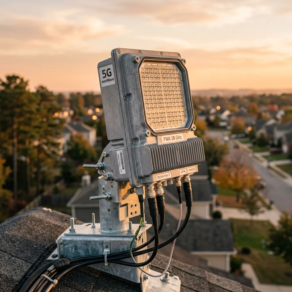
Fiber remains the gold standard for last-mile broadband, but the economics of trenching, permitting, and splicing make it prohibitively expensive in many suburban and rural deployments. Fixed Wireless Access (FWA) at 28 GHz offers a compelling alternative: gigabit-class throughput delivered wirelessly from a base station to a rooftop or window-mounted Customer Premises Equipment (CPE) unit. The RF engineering challenge is straightforward to state and difficult to execute. You must close a link budget across 200 to 2,000 meters of open air while contending with rain fade, foliage attenuation, building penetration loss, and the thermal noise floor of a subscriber unit that costs less than $300.
The 28 GHz Propagation Environment
At 28 GHz, free-space path loss (FSPL) at 500 meters is approximately 121 dB. Compare that to 3.5 GHz mid-band 5G, where the same distance produces only 103 dB of FSPL. The additional 18 dB of loss at 28 GHz must be overcome with antenna gain, transmit power, or both. Atmospheric absorption at 28 GHz is negligible (approximately 0.07 dB/km), so it does not meaningfully affect link budgets at FWA distances.
Rain is the dominant variable impairment. At 28 GHz, rain attenuation follows an approximate power-law relationship with rain rate. ITU-R P.838 provides the specific attenuation coefficients:
| Rain Rate (mm/hr) | Specific Atten. (dB/km) | 500m Link Margin | 1km Link Margin | Availability Impact |
|---|---|---|---|---|
| 5 (light) | 1.2 | 0.6 dB | 1.2 dB | Negligible |
| 25 (moderate) | 5.5 | 2.8 dB | 5.5 dB | 99.99% achievable |
| 50 (heavy) | 10.1 | 5.1 dB | 10.1 dB | Requires margin planning |
| 100 (tropical) | 18.4 | 9.2 dB | 18.4 dB | Outage probable at distance |
For a 99.99% availability target in ITU Rain Zone K (much of the eastern United States), the 0.01% exceedance rain rate is approximately 42 mm/hr. This translates to roughly 8 dB/km of rain attenuation. A 1 km FWA link in this zone needs 8 dB of rain fade margin on top of the clear-sky budget.
Building the Link Budget
A practical 28 GHz FWA link budget starts at the base station transmitter and ends at the CPE receiver's baseband processor. Every component in the RF chain contributes gain or loss, and the cumulative sum determines whether the received signal exceeds the minimum demodulation threshold.
Base Station Side
The base station antenna is typically a 256-element phased array capable of forming multiple simultaneous beams. Each beam provides 25 to 28 dBi of gain with a 3 dB beamwidth of approximately 5 to 7 degrees. Transmit power per beam is 30 to 36 dBm EIRP, constrained by FCC Part 30 regulations that limit the maximum EIRP density to 75 dBm/100 MHz at the antenna.
The transmitter chain includes a GaN power amplifier, beamforming network with per-element phase and amplitude control, calibration paths, and a diplexer or circulator for TDD operation. Cable losses between the radio unit and antenna array are minimized by integrating the radio directly behind or within the antenna panel, an architecture known as Active Antenna Unit (AAU).
CPE Side
The subscriber CPE antenna is smaller by necessity: a 64 or 128-element phased array producing 20 to 24 dBi of gain. The CPE must align its beam toward the base station, either through an installation procedure or automatic beam tracking. The receiver noise figure is typically 7 to 9 dB, higher than a base station LNA but acceptable given the cost target.
Link Budget Worked Example (500m, clear sky): TX EIRP: +36 dBm. FSPL at 500m: -121 dB. Atmospheric loss: -0.04 dB. CPE antenna gain: +22 dBi. CPE cable/connector loss: -2 dB. Received power: -65 dBm. Required SNR for 256-QAM (1 Gbps): -72 dBm (assuming 400 MHz BW, 9 dB NF). Link margin: 7 dB clear-sky. After 5 dB rain fade margin: 2 dB residual margin.
That 2 dB residual margin is razor thin. It leaves almost nothing for CPE misalignment, connector degradation, or foliage growth between seasonal installation and midsummer leaf density. This is why 28 GHz FWA operators specify maximum cell radii of 300 to 500 meters for gigabit-class service, and why precision RF terminations in the test chain are essential during base station commissioning to ensure every decibel of specified transmit power reaches the antenna.
The Foliage Problem
Trees are the silent adversary of 28 GHz FWA. A single deciduous tree in full leaf produces 15 to 25 dB of attenuation at 28 GHz, depending on species, canopy depth, and moisture content. A stand of trees along a residential street can produce 30 to 40 dB of aggregate loss, which is enough to completely close the link.
Seasonal variation compounds the problem. A link installed in January when trees are bare may show 25 dB of margin. By July, leaf growth consumes that margin entirely. RF planners must account for worst-case foliage conditions, not installation-day conditions.
- Rooftop CPE with clear line of sight avoids foliage entirely but requires professional installation on every home.
- Window-mounted CPE adds 10 to 25 dB of building penetration loss (depending on glass type), making the link budget nearly impossible at distances beyond 200 meters.
- Elevated base station placement (above the tree canopy) improves the geometry but increases infrastructure cost and wind loading.
- Relay nodes on utility poles can shorten the link distance below the foliage threshold, at the cost of added hardware and backhaul capacity.
Antenna Design Trade-offs at the CPE
The CPE antenna represents the most constrained element in the FWA system. It must deliver enough gain to close the link, fit within a form factor acceptable for residential deployment, and cost less than the base station antenna by an order of magnitude.
| CPE Antenna Type | Elements | Gain (dBi) | Scan Range | Relative Cost |
|---|---|---|---|---|
| Patch array (fixed beam) | 64 | 22 | Fixed | $ |
| Patch array (steered) | 64 | 20-22 | ±30° | $$ |
| Dual-panel steered | 128 | 23-25 | ±60° (combined) | $$$ |
| Horn + mechanical gimbal | 1 | 24-28 | ±90° (motor) | $$$ |
Most commercial FWA CPEs from Qualcomm-based platforms use a 64-element steered patch array. The beam steering capability allows the CPE to compensate for installation angle errors and to track the base station beam during wind-induced antenna sway. At RF Essentials, our engineering team works with CPE developers who need WR-28 waveguide bends and transitions for validating 28 GHz CPE antenna patterns in anechoic chambers during the design phase.
System-Level Realities
Capacity vs. Coverage
A 28 GHz FWA base station with 400 MHz of bandwidth can deliver approximately 2 to 4 Gbps of aggregate sector throughput using 256-QAM and 4-layer MIMO. Dividing that among subscribers determines the per-user experience. Fifty homes per sector at 100 Mbps each requires 5 Gbps, which is already beyond the single-sector capacity. Operators address this with narrower beams (more sectors per site), carrier aggregation across multiple 28 GHz channels, or a combination of 28 GHz and sub-6 GHz carriers.
Backhaul Requirements
Every FWA base station needs a backhaul connection capable of carrying the aggregate throughput of all its sectors. At full capacity, a multi-sector 28 GHz FWA site can generate 10 to 20 Gbps of backhaul demand. Fiber is the preferred backhaul medium, but where fiber is unavailable, operators use E-band (71-86 GHz) or V-band (60 GHz) wireless backhaul links with WR-12 or WR-15 waveguide hardware.
Interference Management
In dense FWA deployments, inter-cell interference becomes a limiting factor. Narrow beams help, but sidelobe levels from adjacent sectors can elevate the noise floor at the CPE. Coordinated beamforming and time-domain scheduling between neighboring base stations mitigate interference, but they require accurate channel state information that is difficult to maintain in a dynamic outdoor environment.
Where 28 GHz FWA Makes Economic Sense
The sweet spot for 28 GHz FWA is suburban areas with moderate housing density (8 to 30 homes per acre), clear line of sight from elevated base station locations, and limited or no existing fiber infrastructure. In these scenarios, the cost of deploying FWA (base station hardware plus per-home CPE installation) is 40 to 70% lower than fiber-to-the-home construction, with comparable performance for most residential broadband use cases.
For operators evaluating 28 GHz FWA, the link budget is not just an engineering exercise. It is the document that determines whether the business case closes. Every decibel of link margin translates directly to cell radius, subscriber density, and revenue per site. That is why the precision of every component in the RF chain, from the base station PA to the CPE LNA to the calibration terminations used during antenna pattern verification, matters to the bottom line.
RF Essentials manufactures WR-28 waveguide components for 28 GHz test and development: straight sections, bends, twists, terminations, adapters, and calibration standards. All products are CNC machined in the USA with tolerances specified for Ka-band performance.
Frequently Asked Questions
What dominates the 28 GHz fixed wireless access link budget?
Rain and foliage dominate, not atmospheric absorption, which is only about 0.07 dB per kilometer. Free-space path loss at 500 meters is roughly 121 dB, about 18 dB worse than 3.5 GHz mid-band. A 99.99 percent availability target in much of the eastern United States corresponds to a 42 mm per hour rain rate and roughly 8 dB per kilometer of rain attenuation, so margin planning centers on rain zones and a clear line of sight.
Why does foliage matter so much for 28 GHz fixed wireless?
A single deciduous tree in full leaf adds 15 to 25 dB at 28 GHz, and a stand of trees along a street can add 30 to 40 dB, which is enough to close a link entirely. The effect is seasonal: a link installed in January with 25 dB of margin can lose all of it by July as leaves fill in. Planners must design for worst-case foliage rather than installation-day conditions.
Why are 28 GHz fixed wireless cells limited to 300 to 500 meters?
A worked 500 meter clear-sky budget leaves only about 7 dB of margin, and after 5 dB of rain fade just 2 dB remains, far too little for CPE misalignment, connector aging, or seasonal foliage growth. That razor-thin residual margin is why operators cap cell radius for gigabit-class service and why precision terminations in the commissioning test chain matter, so every specified decibel of transmit power actually reaches the antenna.