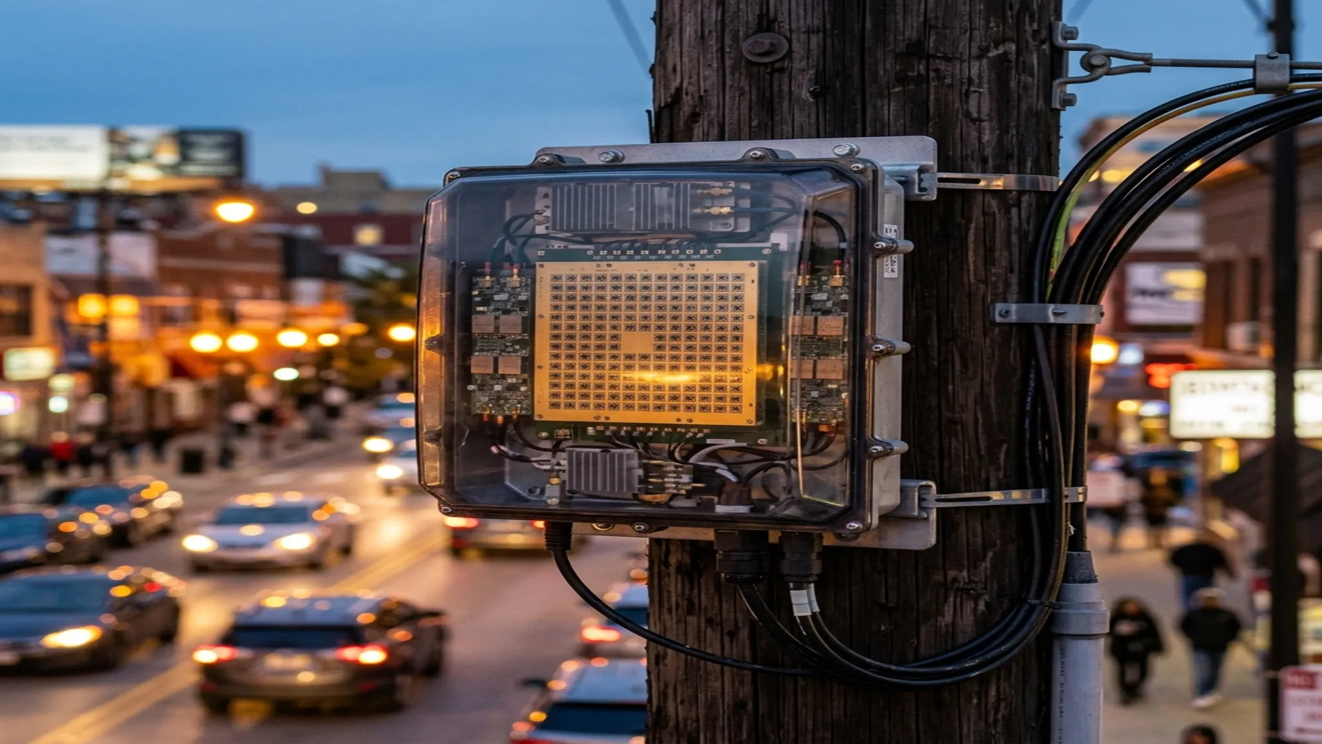
A 5G mmWave small cell looks simple from the outside: a weatherproof box the size of a pizza box, bolted to a pole. Inside that box is the most complex RF front end ever mass-produced. A single FR2 small cell panel contains 256 to 1,024 antenna elements, each driven by its own transmit/receive path with independent phase and amplitude control, all operating at 28 or 39 GHz with bandwidths up to 400 MHz and beam-switching rates measured in microseconds.
This article breaks down the RF hardware stack inside an FR2 small cell, from the baseband digital interface to the antenna aperture. If you are designing, integrating, testing, or supplying components for mmWave 5G infrastructure, this is the architecture you need to understand.
1. The FR2 Frequency Bands
3GPP defines two primary FR2 (Frequency Range 2) bands for 5G NR mmWave operation:
| Band | 3GPP Designation | Frequency Range | Max Channel BW | Primary Markets |
|---|---|---|---|---|
| 28 GHz | n257 / n261 | 26.5-29.5 GHz / 27.5-28.35 GHz | 400 MHz | US, Japan, Korea |
| 39 GHz | n260 | 37.0-40.0 GHz | 400 MHz | US |
| 26 GHz | n258 | 24.25-27.5 GHz | 400 MHz | Europe, Asia |
The choice of band determines the waveguide size (WR-28 for Ka-band, WR-22 for the upper range), the antenna element spacing (approximately 5.4 mm at 28 GHz, 3.8 mm at 39 GHz), and the propagation characteristics (39 GHz has roughly 3 dB more free-space path loss than 28 GHz for the same distance).
2. The RF Front End Architecture
A modern FR2 small cell panel uses a hybrid beamforming architecture that splits the signal processing between the digital domain (baseband) and the analog domain (RF front end). The signal chain from baseband to antenna consists of five major blocks:
Block 1: Digital Baseband and DAC/ADC
The baseband processor generates the 5G NR waveform (OFDM with up to 400 MHz bandwidth) at an intermediate frequency (IF), typically in the 3 to 5 GHz range. Digital-to-analog converters (DACs) with 12 to 14 bits of resolution and sampling rates above 10 GSPS convert the digital waveform to analog IF. On the receive side, ADCs with similar specifications digitize the received IF signal.
Block 2: IF-to-RF Upconversion / Downconversion
A frequency converter translates the IF signal to the target RF frequency (28 or 39 GHz) using a local oscillator (LO) and mixer chain. The LO is typically generated by a PLL synthesizer locked to a stable reference, with phase noise requirements below -100 dBc/Hz at 100 kHz offset to support 256-QAM modulation. The upconverter output feeds a distribution network that splits the signal to multiple beamforming channels.
Block 3: Beamforming IC (BFIC)
The beamforming IC is the heart of the front end. Each BFIC controls 4 to 16 antenna elements, providing independent phase shift (6 to 8 bits, or 5.6° to 1.4° resolution) and amplitude control (5 to 6 bits) for each element on both transmit and receive paths. A single small cell panel uses 16 to 64 BFICs to control the full array.
Key Suppliers: The BFIC market is dominated by Analog Devices (via the Anokiwave acquisition), Renesas, Qualcomm, and Samsung's in-house designs. These ICs are fabricated in SiGe BiCMOS or advanced CMOS (14nm/7nm) processes and integrate the phase shifters, variable gain amplifiers, T/R switches, and power combiners into a single package, typically 8mm x 8mm or smaller.
Block 4: Power Amplifier and Low-Noise Amplifier
Each transmit path requires a power amplifier to boost the signal to the antenna. In FR2 systems, the PA is integrated into or closely coupled with the BFIC. Typical specifications per element:
| Parameter | 28 GHz | 39 GHz |
|---|---|---|
| PA output power (per element) | 12 to 15 dBm | 10 to 13 dBm |
| PA efficiency (PAE) | 25 to 35% | 20 to 30% |
| LNA noise figure | 3.0 to 4.0 dB | 3.5 to 5.0 dB |
| LNA gain | 15 to 20 dB | 12 to 18 dB |
| T/R switching time | < 1 μs | < 1 μs |
The aggregate EIRP (Effective Isotropic Radiated Power) of the full panel is the sum of all element contributions, coherently combined through beamforming. A 256-element panel with 13 dBm per element and 24 dBi array gain produces approximately 61 dBm EIRP, sufficient for cell radii of 150 to 300 meters in urban environments.
Block 5: Antenna Array and Feed Network
The antenna elements are typically patch antennas or slot-coupled microstrip antennas fabricated directly on the PCB or on a separate antenna-in-package (AiP) substrate. Element spacing is approximately λ/2 (5.4 mm at 28 GHz) to avoid grating lobes. The feed network distributes the RF signal from each BFIC output to the corresponding antenna elements through microstrip or stripline transmission lines.
3. Thermal Challenges at mmWave
A 256-element FR2 panel dissipates 30 to 80 watts of heat in a sealed, outdoor enclosure with no moving parts. The PA efficiency of 25 to 35% means that for every watt of RF power radiated, 2 to 3 watts of heat must be removed. The thermal design must maintain junction temperatures below 125°C across an ambient range of -40°C to +55°C.
Thermal solutions include aluminum heat spreaders bonded to the BFIC packages, thermally conductive PCB cores (aluminum or copper-clad), and passive convection/radiation from the enclosure exterior. Some high-power designs use heat pipes or vapor chambers to transport heat from the BFIC hot spots to the enclosure walls.
4. Test and Measurement: Where Waveguide Enters
While the production small cell is a fully integrated module, the development and test environment requires discrete RF connections at every stage. Over-the-air (OTA) test chambers for FR2 use WR-28 waveguide-fed horn antennas as reference probes. Conducted testing of BFICs and sub-arrays uses WR-28 waveguide-to-coax adapters, precision terminations, and calibration standards. Every FR2 test bench requires:
- WR-28 calibration kits: Open, short, load, and thru standards for network analyzer calibration at Ka-band
- WR-28 horn antennas: Standard gain horns for OTA testing with known gain patterns
- WR-28 terminations: Matched loads for receiver sensitivity measurements and isolation testing
- WR-28 to 2.92mm adapters: Waveguide-to-coax transitions for connecting to test instruments
- WR-22 equivalents: For 39 GHz (n260) testing, the waveguide size shifts to WR-22
RF Essentials manufactures precision WR-28 and WR-22 waveguide components including straight sections, bends, twists, terminations, horn antennas, and adapters for 5G FR2 development and production test. All products are made in the USA.
Frequently Asked Questions
What are the FR2 millimeter-wave bands for 5G?
3GPP defines several FR2 bands: n257 and n261 around 28 GHz for the US, Japan, and Korea; n260 at 37 to 40 GHz for the US; and n258 at 24.25 to 27.5 GHz for Europe and Asia, each with channels up to 400 MHz. The chosen band sets the waveguide size, WR-28 at Ka-band, the element spacing, about 5.4 mm at 28 GHz and 3.8 mm at 39 GHz, and the propagation, with 39 GHz carrying roughly 3 dB more path loss than 28.
What is a beamforming IC and how many does a small cell need?
The beamforming IC is the heart of the front end. Each one controls 4 to 16 antenna elements with independent phase, at 6 to 8 bits, and amplitude, at 5 to 6 bits, on both transmit and receive, integrating phase shifters, variable-gain amplifiers, T/R switches, and combiners into a package around 8 by 8 mm. A single panel uses 16 to 64 BFICs from suppliers like Analog Devices, Renesas, and Qualcomm to drive its full 256 to 1,024 element array.
Where does waveguide enter FR2 small cell work?
It shows up in test and measurement. Over-the-air FR2 chambers use WR-28 waveguide-fed horn antennas as reference probes, and conducted testing of beamforming ICs and sub-arrays uses WR-28-to-coax adapters, precision terminations, and calibration standards. Every Ka-band test bench needs WR-28 calibration kits with open, short, load, and thru standards, standard gain horns, and matched loads to verify the integrated module.