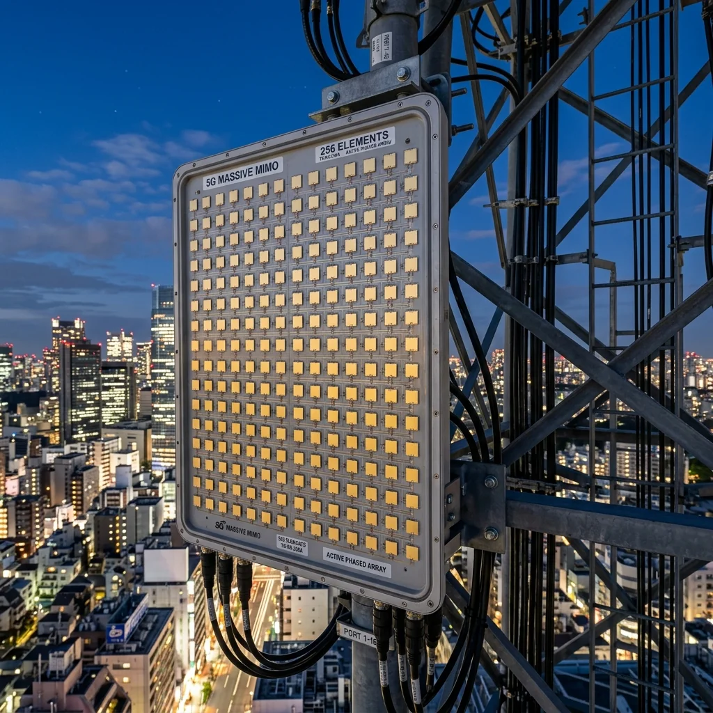
At 39 GHz, the wavelength is 7.7 mm. An antenna element is roughly half that: 3.8 mm. You can fit 256 elements into a panel smaller than a laptop screen. This density is what makes millimeter-wave beamforming both possible and necessary. Without beamforming gain, the path loss at 39 GHz would limit useful communication distances to a few tens of meters. With a 256-element array producing 25 to 28 dBi of gain, the same transmitter can reach 500 meters or more. The question is not whether to beamform, but how: analog, digital, or a hybrid of both.
Analog Beamforming: One RF Chain, Many Elements
In an analog beamforming architecture, all antenna elements share a single RF chain. Phase shifters at each element (or small groups of elements) steer the beam by adjusting the relative phase of the signal fed to each element. The phase-shifted signals are combined in the analog domain before a single ADC digitizes the composite signal.
The advantage is cost and power consumption. One RF chain means one set of amplifiers, one mixer, one ADC. For a 256-element array, this eliminates 255 redundant receiver chains. The power consumption of the array is dominated by the phase shifters (a few milliwatts each) and the single RF chain (roughly 1 to 3 watts).
| Parameter | Analog | Digital | Hybrid (sub-array) |
|---|---|---|---|
| RF chains per 256 elements | 1 | 256 | 8-32 |
| Simultaneous beams | 1 | Up to 256 | 8-32 |
| Power consumption | Low (3-5 W) | Very high (50-200 W) | Moderate (15-40 W) |
| ADC count | 1 (or 2 for dual-pol) | 256 (or 512) | 8-32 (or 16-64) |
| Beam flexibility | Single beam, steered | Arbitrary patterns | Multiple beams per panel |
| Null steering | Limited | Full (per-element) | Sub-array level |
| Calibration complexity | Low | Very high | Moderate |
The limitation of analog beamforming is that it produces only one beam at a time. In a multi-user scenario, the base station must time-division multiplex between users, pointing the beam at each user sequentially. This reduces the aggregate throughput proportionally to the number of users served. Additionally, analog beamforming cannot place spatial nulls independently of the main beam direction, limiting its ability to reject interference.
Digital Beamforming: Maximum Flexibility, Maximum Cost
Digital beamforming assigns a dedicated RF chain and ADC to every antenna element. The digitized signals from all elements are combined in the digital domain using complex weights (amplitude and phase per element per frequency bin). This enables simultaneous formation of multiple independent beams, each pointed at a different user, each with independently optimized sidelobe patterns and null placements.
At 39 GHz with 400 MHz of bandwidth, each ADC must operate at 800 MS/s or higher with 10 to 12 bits of resolution. For a 256-element array, that is 256 ADCs producing a combined data rate exceeding 2 terabits per second. The FPGA or ASIC processing this data stream must perform 256-point complex multiply-accumulate operations across every frequency bin in real time. The power consumption of the digital processing alone can exceed 100 watts.
The Thermal Challenge: A 256-element digital beamformer at 39 GHz dissipates 100 to 200 watts in a panel roughly 200 mm × 200 mm. That is a power density of 2,500 to 5,000 W/m², comparable to the surface of a CPU die. Thermal management, through heat sinks, forced air, or liquid cooling, becomes a primary mechanical design constraint. This is one reason why fully digital architectures are currently used only in fixed base station equipment, not in mobile handsets or small form-factor CPE devices.
Hybrid Beamforming: The Practical Compromise
Hybrid beamforming divides the antenna array into sub-arrays, each containing 8 to 32 elements. Each sub-array has its own RF chain and ADC, while the elements within each sub-array are combined using analog phase shifters. The digital processing then operates on the sub-array outputs rather than on individual element signals.
A 256-element array with 16-element sub-arrays has 16 RF chains and 16 ADCs. This allows the formation of up to 16 simultaneous beams (one per sub-array degree of freedom), with analog beam steering providing the fine angular resolution within each sub-array's pattern. The power consumption is roughly 15 to 40 watts, an order of magnitude below full digital but significantly above pure analog.
Sub-Array Partitioning Strategies
- Localized sub-arrays: each sub-array consists of a contiguous block of adjacent elements. Simple to route and manufacture, but the sub-array beam is wider than the full array beam, limiting the angular resolution of each digital channel.
- Interleaved sub-arrays: elements from each sub-array are distributed across the full aperture. Each sub-array has the same beamwidth as the full array, providing better angular resolution per digital channel. However, the routing of RF signals from distributed elements to a common RF chain is significantly more complex.
- Polarization-based sub-arrays: separate sub-arrays for horizontal and vertical polarization, enabling polarization-division multiplexing in addition to spatial multiplexing.
Most commercial 5G base station equipment deployed at 39 GHz uses hybrid beamforming with localized sub-arrays. Qualcomm's QTM545 mmWave antenna module, used in many base station designs, integrates 4 sub-arrays of 16 elements each in a single package, providing 4 simultaneous beams per module. Multiple modules are combined to create larger arrays with more beams. The waveguide test components used to characterize these modules must maintain calibration-grade accuracy across the full 37 to 40 GHz band.
Phase Shifter Technologies at 39 GHz
The phase shifter is the core component of any analog or hybrid beamforming array. At 39 GHz, three technologies compete:
| Type | Resolution | Insertion Loss | Switching Speed | Power |
|---|---|---|---|---|
| Switched-line (CMOS) | 5-6 bits | 8-14 dB | < 1 ns | < 1 mW |
| Reflective-type (SiGe) | Continuous | 5-8 dB | < 1 ns | 5-20 mW |
| MEMS | 3-5 bits | 1-3 dB | 10-100 μs | < 0.1 mW |
CMOS switched-line phase shifters dominate commercial 5G deployments because they integrate directly with the CMOS beamformer ASIC, eliminating the need for separate phase shifter components. The high insertion loss (8 to 14 dB) is compensated by the PA gain within the same ASIC. MEMS phase shifters offer dramatically lower insertion loss but switch too slowly for the beam tracking requirements of mobile 5G, where beam updates must occur within hundreds of microseconds.
At RF Essentials, our engineering team supports antenna developers who need WR-28 and WR-22 waveguide components for characterizing beamforming arrays in anechoic chambers and compact antenna test ranges. The calibration terminations and loads used in these measurements must maintain specified performance across the full Ka-band to ensure accurate beam pattern characterization.
WR-28 and WR-22 waveguide components for 39 GHz beamforming array characterization: terminations, loads, couplers, bends, and calibration standards. All CNC machined in the USA.
Frequently Asked Questions
What is the core trade-off between analog, digital, and hybrid beamforming at 39 GHz?
Analog beamforming shares one RF chain across all elements, keeping power down to 3 to 5 W but allowing only a single steered beam with limited nulling. Digital beamforming gives every element its own RF chain and ADC for arbitrary multi-beam patterns, at 50 to 200 W and enormous data rates. Hybrid beamforming groups elements into sub-arrays for a practical middle ground around 15 to 40 W, which is what most commercial 39 GHz base stations use.
Why is fully digital beamforming hard to deploy at 39 GHz?
With 400 MHz of bandwidth, each of 256 ADCs must run at 800 MS/s or more with 10 to 12 bits, combining to over 2 terabits per second that an FPGA or ASIC must process in real time. The panel also dissipates 100 to 200 W in a roughly 200 by 200 mm area, a power density comparable to a CPU die. That thermal and data load confines fully digital arrays to fixed base stations rather than handsets.
What is sub-array partitioning in hybrid beamforming?
The array is divided into sub-arrays of 8 to 32 elements, each with its own RF chain, while elements within a sub-array are combined with analog phase shifters. Localized sub-arrays use contiguous blocks, which are simple to route but give a wider sub-array beam. Interleaved sub-arrays spread elements across the aperture for full-array beamwidth at the cost of complex routing. Polarization-based sub-arrays split horizontal and vertical. Most 39 GHz equipment uses localized sub-arrays.