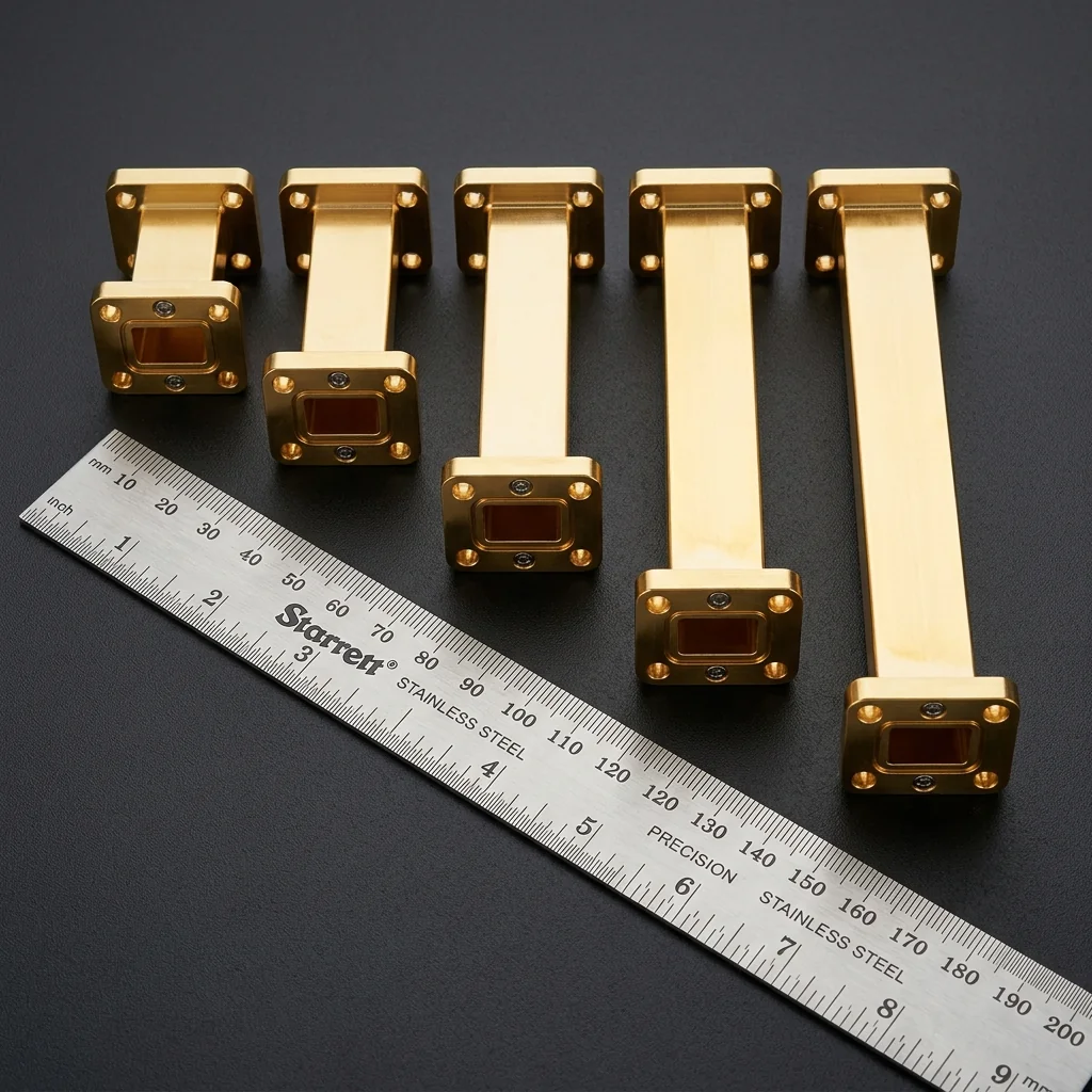
A waveguide straight section appears to be the simplest component in an RF system: a length of rectangular metal tube with a flange on each end. At WR-90 (8.2 to 12.4 GHz), that simplicity is largely real. The 22.86 mm by 10.16 mm aperture dimensions tolerate ±50 μm of machining variation without measurable impact on performance. At WR-10 (75 to 110 GHz), the aperture shrinks to 2.54 mm by 1.27 mm, and a ±10 μm dimensional error changes the cutoff frequency by 300 MHz. The straight section is no longer simple; it is a precision component where material selection, surface finish, and flange flatness determine whether the system meets its performance budget.
Dimensional Tolerances by Precision Grade
The waveguide industry recognizes three informal precision grades, each tied to manufacturing process capability and intended application. No universal standard defines these grades, but the tolerance ranges below are representative of what major manufacturers (Flann Microwave, Aerowave, Millimeter Wave Products) specify.
| Grade | Aperture Tolerance | Surface Roughness (Ra) | Flange Flatness | Application |
|---|---|---|---|---|
| Commercial | ±25-50 μm | 0.8-1.6 μm | 10-25 μm | Production systems, telecom |
| Standard | ±10-25 μm | 0.4-0.8 μm | 5-10 μm | Lab equipment, test benches |
| Instrumentation | ±5-10 μm | 0.1-0.4 μm | 2-5 μm | Metrology, calibration kits |
The tolerance grade determines insertion loss, return loss, and phase repeatability. A commercial-grade WR-10 straight section with ±50 μm aperture tolerance produces a return loss of 25 to 30 dB at band center, degrading to 18 to 22 dB at band edges. An instrumentation-grade section with ±5 μm tolerance maintains 35 to 40 dB return loss across the full band. For calibration and measurement applications, where the straight section serves as a reference standard, only instrumentation grade is acceptable.
Surface Roughness and Insertion Loss
Electromagnetic current flows in a thin skin on the inner walls of the waveguide. The skin depth at 94 GHz in copper is approximately 0.21 μm. Surface roughness comparable to or larger than the skin depth forces the current to follow a longer, irregular path, increasing resistive loss. The relationship between surface roughness and excess loss follows the Hammerstad-Jensen model:
Where: Ra = arithmetic mean roughness, δ = skin depth
At 94 GHz (δ = 0.21 μm):
Ra = 0.1 μm → loss increase = 5%
Ra = 0.4 μm → loss increase = 38%
Ra = 0.8 μm → loss increase = 72%
Ra = 1.6 μm → loss increase = 86%
For WR-10 waveguide operating at 94 GHz, the smooth-wall theoretical insertion loss is approximately 0.12 dB/cm. A commercial-grade section with Ra = 1.6 μm increases this to 0.22 dB/cm. Over a 10 cm straight section, the difference is 1.0 dB, significant in systems where every tenth of a dB matters (radar receivers, radiometers, calibration paths). An instrumentation-grade section with Ra = 0.1 μm adds only 0.006 dB/cm of excess loss, indistinguishable from the theoretical minimum.
Gold Plating and Loss: Gold plating (0.5 to 2.0 μm thickness) prevents oxidation and ensures stable, repeatable contact at waveguide flanges. However, gold's conductivity (4.1 × 10⁷ S/m) is 30% lower than copper (5.96 × 10⁷ S/m). A gold-plated waveguide has approximately 0.015 dB/cm higher insertion loss than bare copper at 94 GHz. The trade-off is worthwhile: bare copper oxidizes within weeks in ambient air, and the oxide layer introduces higher loss than the gold coating. Silver plating offers the best conductivity (6.3 × 10⁷ S/m) but tarnishes rapidly and is reserved for hermetically sealed assemblies.
Material Selection
Copper and Copper Alloys
C101 (oxygen-free high-conductivity copper) is the benchmark material for low-loss waveguide. Its conductivity of 5.96 × 10⁷ S/m is the highest of any practical waveguide material. Machining is straightforward with CNC milling or wire EDM. The primary limitation is mechanical: copper is soft (Brinell hardness 35-65), which makes threaded flange holes prone to stripping under repeated assembly cycles. Most copper waveguide uses helicoil inserts or captive hardware to address this.
Aluminum
6061-T6 aluminum is the standard material for commercial and production waveguide. Its conductivity (2.5 × 10⁷ S/m) is 42% of copper, increasing insertion loss by approximately 0.04 dB/cm at 94 GHz compared to copper. The mechanical advantages compensate: aluminum is lighter (2.7 g/cm³ vs. 8.96 g/cm³), machines faster, holds tighter tolerances in thin-wall sections, and resists galling at flange interfaces. For production systems where weight and cost matter more than the last 0.05 dB of loss, aluminum is the default choice.
Brass and Stainless Steel
C360 free-machining brass appears in legacy waveguide components and custom configurations where complex internal geometries (couplers, filters, orthomode transducers) require extensive machining. Its conductivity (1.6 × 10⁷ S/m) produces higher loss than aluminum, but the superior machinability of free-machining brass allows features that would be difficult in copper. Stainless steel waveguide exists only for specialized environments (cryogenic, ultra-high vacuum, corrosive atmospheres) where no other material survives.
Flange Standards and Alignment
Two flange families dominate rectangular waveguide connections: UG (military-heritage, screw-type) and UBR (British, 2-bolt). At mmWave frequencies, precision alignment is achieved by the flange pilot diameter (a raised circular boss on one flange mating with a corresponding recess on the other). The pilot provides centering to within ±10 μm, which is adequate for WR-28 (26.5 to 40 GHz) but marginal for WR-10.
At W-band and above, IEEE 1785.1 precision waveguide flanges replace the traditional UG system. These flanges use precision dowel pins (1.5748 mm diameter, ±2.5 μm tolerance) pressed into one flange that engage reamed holes in the mating flange. The pin alignment system achieves ±3 μm repeatability, which is required to maintain 35+ dB return loss at the connection. Every disconnection and reconnection of a UG-style flange at W-band risks a 2 to 5 dB degradation in return loss due to alignment shift. IEEE 1785.1 flanges maintain specification across hundreds of mating cycles.
| Waveguide | Frequency | UG Flange | IEEE 1785.1 | Aperture (mm) |
|---|---|---|---|---|
| WR-28 | 26.5-40 GHz | UG-599/U | N/A | 7.112 × 3.556 |
| WR-19 | 40-60 GHz | UG-383/U | IEEE 1785.1-19 | 4.775 × 2.388 |
| WR-15 | 50-75 GHz | UG-385/U | IEEE 1785.1-15 | 3.759 × 1.880 |
| WR-12 | 60-90 GHz | UG-387/U | IEEE 1785.1-12 | 3.099 × 1.549 |
| WR-10 | 75-110 GHz | UG-387/U | IEEE 1785.1-10 | 2.540 × 1.270 |
RF Essentials stocks waveguide straight sections in standard and instrumentation grades across all sizes from WR-28 through WR-3. Custom lengths, non-standard flanges, and gold or silver plating options are available on request. Related components include precision loads for system calibration and transition adapters for connecting between waveguide sizes.
Precision straight sections, bends, twists, and adapters. Instrumentation-grade WR-10 through WR-28 with IEEE 1785.1 flange options.
Frequently Asked Questions
What precision grades exist for waveguide straight sections?
The industry recognizes three informal grades. Commercial holds the aperture to plus or minus 25 to 50 micrometers with 0.8 to 1.6 micrometer surface roughness. Standard tightens to 10 to 25 micrometers and 0.4 to 0.8 micrometer roughness. Instrumentation reaches 5 to 10 micrometers and 0.1 to 0.4 micrometer. The grade sets return loss: a commercial WR-10 section gives 25 to 30 dB at band center, while instrumentation grade holds 35 to 40 dB across the full band.
How does surface roughness affect waveguide insertion loss?
Current flows in a thin skin on the inner walls, about 0.21 micrometers deep at 94 GHz in copper. When roughness approaches the skin depth, the current follows a longer, irregular path and resistive loss rises. At 94 GHz, an Ra of 0.1 micrometers adds about 5 percent loss, while 1.6 micrometers adds 86 percent. Over a 10 cm WR-10 section that difference is roughly 1 dB, which matters in radar receivers and calibration paths.
Should waveguide be machined from copper or aluminum?
Copper alloy C101 has the highest conductivity and lowest loss, but it is soft, so threaded flange holes need helicoil inserts to survive repeated assembly. Aluminum 6061-T6 has about 42 percent of copper's conductivity, adding roughly 0.04 dB per cm at 94 GHz, but it is far lighter, machines faster, and holds tighter tolerances in thin walls. For production systems where weight and cost outweigh the last fraction of a dB, aluminum is the default.