Rectangular waveguides are the primary transmission medium for millimeter wave signals. Unlike coaxial cables, which suffer from excessive loss above 40 GHz, waveguides provide a low-loss, high-power-handling path for electromagnetic energy. This article covers the fundamentals of waveguide operation and practical guidance for selecting the right waveguide for your system.
How Rectangular Waveguides Work
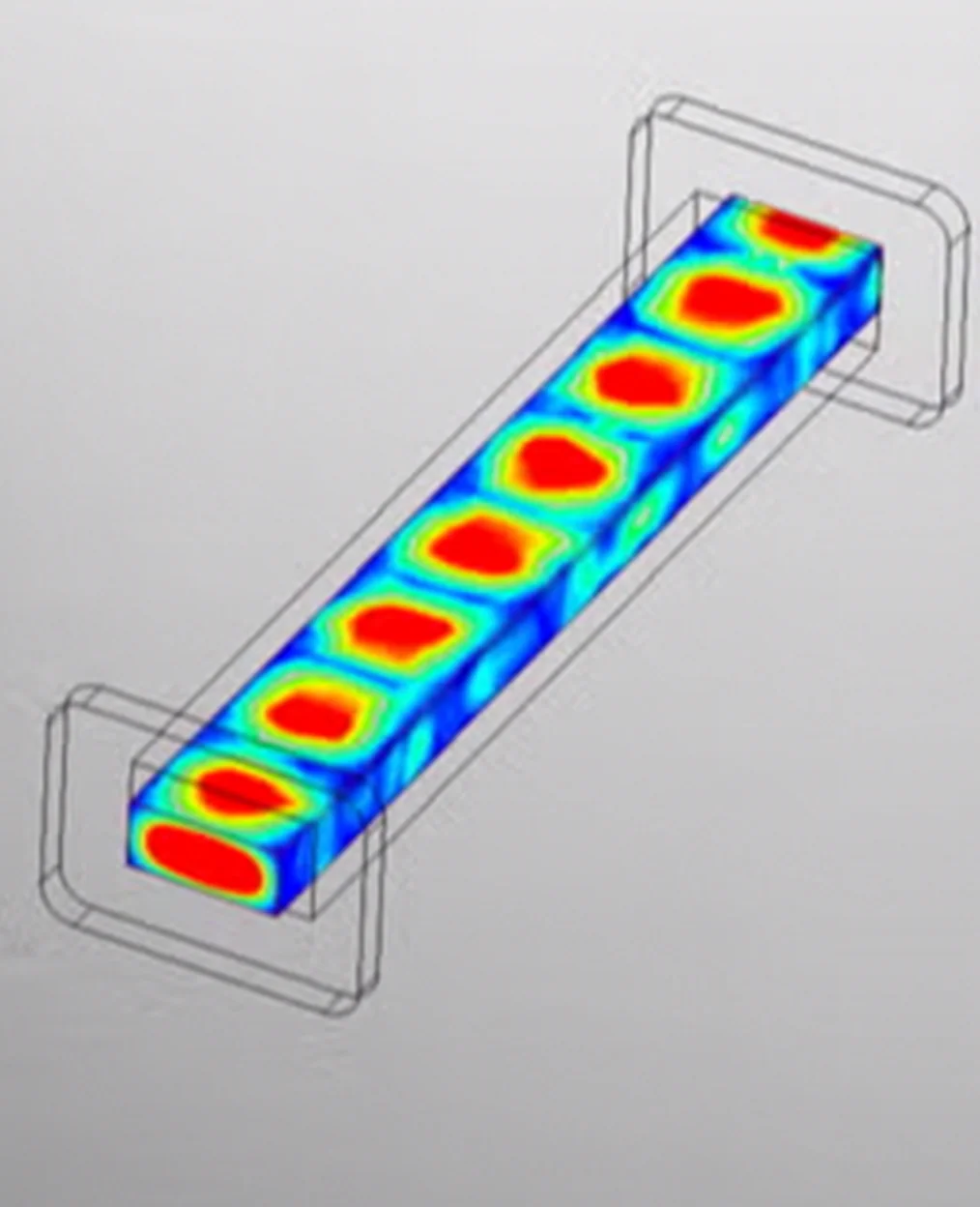
A rectangular waveguide is a hollow metallic tube with a rectangular cross-section. Electromagnetic waves propagate through the interior of the tube by reflecting off the conductive walls. The dominant propagation mode in rectangular waveguide is TE10, where the electric field is oriented across the broad wall of the waveguide.
Each waveguide size has a cutoff frequency determined by its broad wall dimension. Below this frequency, the waveguide cannot propagate energy. Above it, the waveguide supports low-loss transmission across a defined operating bandwidth.
Understanding WR Designations
WR (Waveguide Rectangular) designations identify standard waveguide sizes. The number following "WR" represents the broad wall dimension in hundredths of an inch. For example, WR-28 has a broad wall dimension of 0.280 inches (7.112 mm).
Common WR sizes and their operating bands include:
- WR-28: Ka-Band, 26.5 to 40 GHz
- WR-15: V-Band, 50 to 75 GHz
- WR-10: W-Band, 75 to 110 GHz
- WR-06: D-Band, 110 to 170 GHz
- WR-03: J-Band, 220 to 330 GHz
Factors Affecting Waveguide Performance
Material Selection
The waveguide body material directly impacts conductor loss. OFHC (oxygen-free high conductivity) copper provides the lowest loss for millimeter wave waveguides. The internal surfaces should be smooth and free of machining marks that could scatter RF energy.
Surface Treatment
Gold plating is the standard surface treatment for precision waveguides. It prevents copper oxidation, which would increase surface resistance and degrade insertion loss over time. Gold also provides excellent corrosion resistance for waveguides used in harsh environments.
Flange Selection
Waveguide flanges must mate precisely to avoid air gaps and misalignment at junctions. Standard MIL-DTL-3922 flange patterns ensure interoperability between components from different manufacturers. For smaller WR sizes (WR-10 and below), anti-cocking flanges with alignment pins are recommended.
Minimizing System-Level Insertion Loss
- Use the shortest waveguide runs possible
- Minimize the number of flange connections
- Select OFHC copper waveguides with gold plating
- Avoid flexible waveguide sections in the signal path
- Verify proper flange torque at all connections
Summary
Rectangular waveguides remain the transmission medium of choice for millimeter wave systems above 26 GHz. By understanding WR sizing conventions, material properties, and best practices for system integration, engineers can build waveguide assemblies that deliver optimal performance across their full operating bandwidth.