E-plane waveguide bends are among the most frequently used passive components in millimeter wave assemblies. Understanding how they work, and how to select the right bend for your application, is essential for minimizing signal degradation in waveguide systems.
What Is an E-Plane Bend?
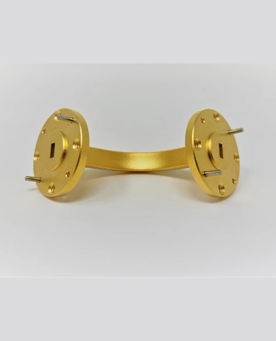
An E-plane bend curves the waveguide along its wider dimension, which corresponds to the electric field (E-field) plane of the dominant TE10 propagation mode. This type of bend redirects the signal path while maintaining the fundamental mode structure of the waveguide.
E-plane bends are typically used when the signal path needs to change direction in the vertical plane relative to the waveguide's broad wall orientation.
How E-Plane Bends Affect Signal Quality
Every waveguide bend introduces two types of signal degradation:
- Insertion loss from the change in waveguide geometry through the bend radius
- Return loss (VSWR) from impedance discontinuities at the bend entrance and exit
The magnitude of both effects depends on the bend radius, the operating frequency, and the manufacturing precision of the component.
Critical Design Parameters
Bend Radius
Larger bend radii produce lower insertion loss and better VSWR. However, larger radii also increase the overall size of the waveguide assembly. For most applications, a bend radius of 2 to 3 times the broad wall dimension provides a good balance between performance and compactness.
Machining Tolerance
The internal waveguide dimensions must remain consistent through the entire bend radius. Variations in cross-sectional dimensions create impedance discontinuities that degrade VSWR. CNC machining with tight tolerances is essential, particularly for WR-10 and smaller sizes.
Surface Finish
The internal surface finish of the bend affects conductor loss. At frequencies above 75 GHz, surface roughness becomes a significant contributor to total insertion loss. Gold-plated OFHC copper provides the best combination of low surface roughness and corrosion resistance.
E-Plane vs. H-Plane Bends
The choice between E-plane and H-plane bends depends on the physical orientation needed in your waveguide assembly. E-plane bends curve along the broad wall (vertical routing), while H-plane bends curve along the narrow wall (horizontal routing). Both types offer similar electrical performance when properly manufactured.
Best Practices for System Integration
- Minimize the number of bends in any signal path
- Use the largest bend radius that fits your mechanical constraints
- Verify flange alignment at each bend junction
- Request VSWR test data for each bend, especially at frequencies above 75 GHz
- Consider integrated bend assemblies to reduce the total number of flange connections
Summary
E-plane bends are essential routing components in millimeter wave systems. Selecting bends with appropriate radius, tight machining tolerances, and gold-plated OFHC copper construction minimizes their impact on signal integrity. For critical applications, always request measured performance data from your component supplier.