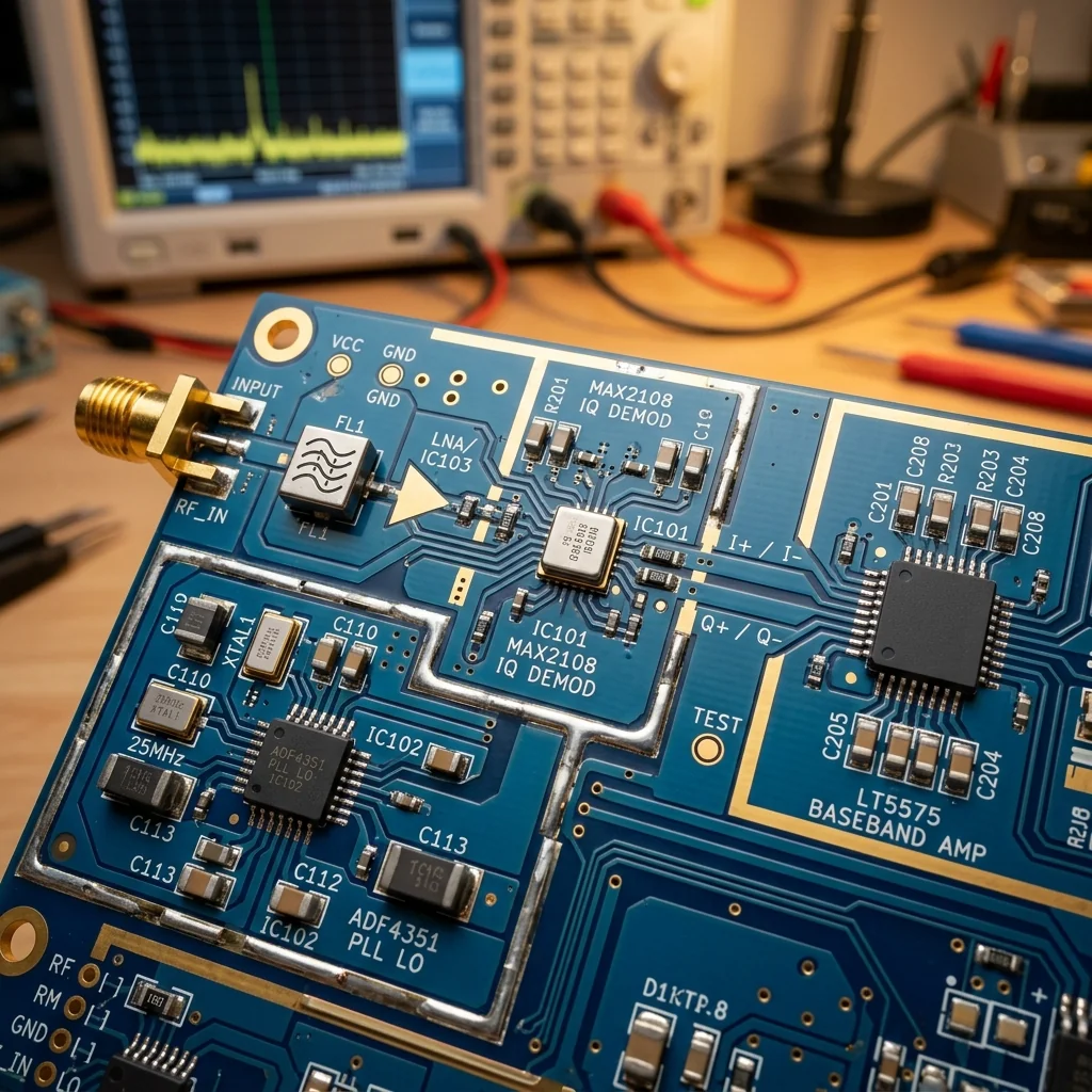
A direct-conversion (zero-IF) receiver downconverts the RF signal to baseband using two mixers driven by local oscillator signals 90° apart. The in-phase (I) and quadrature (Q) outputs carry the real and imaginary components of the complex baseband signal. Any amplitude mismatch or phase deviation from the ideal 90° between these two paths creates an image signal that cannot be separated from the desired signal by filtering alone. At 28 GHz with a practical LO phase error of 3° and amplitude imbalance of 0.5 dB, the resulting image rejection ratio is approximately 31 dB. That limits the achievable EVM to roughly -25 dB, which falls short of the -30 dB required for 64-QAM demodulation in 5G NR FR2.
Sources of I/Q Imbalance
I/Q imbalance originates in four places in the receiver signal chain, and each source contributes differently to the overall image rejection degradation.
LO Quadrature Error
The LO distribution network must deliver signals at exactly 0° and 90° to the I and Q mixers. At microwave frequencies, a Lange coupler or branchline coupler produces the quadrature split. The coupler's amplitude balance and phase quadrature degrade as frequency moves away from the design center. A typical 28 GHz branchline coupler achieves ±0.3 dB amplitude balance and ±2° phase balance over a 1 GHz bandwidth. At the band edges, these errors increase to ±0.8 dB and ±5°.
Mixer Conversion Loss Mismatch
Even with identical mixer designs, manufacturing variation produces 0.2 to 0.5 dB conversion loss difference between the I and Q mixers. At mmWave frequencies, this mismatch is amplified by LO power variation: if the LO divider delivers 0.3 dB more power to one mixer, the conversion loss difference between the two paths can reach 0.8 dB. Matched mixer pairs from the same wafer lot reduce this variation to 0.1 to 0.2 dB.
Baseband Filter Mismatch
The I and Q baseband paths pass through anti-alias filters before the ADCs. These filters must have matched amplitude response (±0.1 dB) and group delay (±0.5 ns) across the signal bandwidth. At wide bandwidths (100 MHz and above), even small component tolerances in the filter networks create frequency-dependent imbalance that is harder to correct than the frequency-flat imbalance from the LO and mixers.
ADC Gain and Timing Mismatch
The two ADCs digitizing the I and Q signals contribute gain offset and sampling time skew. A 1 ps timing skew between the I and Q ADCs at 500 MHz signal bandwidth creates an equivalent phase error of 0.18°. Modern dual-channel ADCs (e.g., Analog Devices AD9082, Texas Instruments ADC12DJ5200) match internal timing to within 0.5 ps, but board-level routing asymmetry adds 1 to 5 ps of skew that must be calibrated in the digital domain.
Frequency-Dependent vs. Frequency-Flat Imbalance: LO and mixer contributions are approximately constant across the signal bandwidth (frequency-flat). Baseband filter and ADC timing contributions vary with frequency (frequency-dependent). Effective correction requires separate algorithms for each type. A system that corrects only frequency-flat imbalance leaves residual image components at the band edges that limit wideband EVM.
Quantifying the Impact
The image rejection ratio (IRR) produced by amplitude imbalance ε (in dB) and phase imbalance Δφ (in degrees) follows the relationship:
Example: ε = 0.5 dB, Δφ = 3° → IRR ≈ 31 dB
Example: ε = 1.0 dB, Δφ = 5° → IRR ≈ 24 dB
Example: ε = 0.1 dB, Δφ = 1° → IRR ≈ 45 dB (after digital correction)
| Modulation | Required EVM | Minimum IRR | Max Phase Error | Max Amp. Error |
|---|---|---|---|---|
| QPSK | -15 dB | 17 dB | 10° | 2.0 dB |
| 16-QAM | -22 dB | 25 dB | 5° | 1.0 dB |
| 64-QAM | -30 dB | 33 dB | 2° | 0.3 dB |
| 256-QAM | -35 dB | 38 dB | 1° | 0.15 dB |
Correction Methods
Pilot-Based Estimation
In communication systems with known pilot symbols (5G NR, Wi-Fi, LTE), the receiver estimates the I/Q imbalance parameters from the received pilot constellation. The pilot symbols are transmitted at known amplitudes and phases; any distortion in the received pilot pattern reveals the amplitude and phase imbalance. A least-squares estimator operating on 64 to 256 pilot symbols achieves imbalance estimates accurate to ±0.05 dB amplitude and ±0.2° phase in SNR conditions above 15 dB. The estimates update every frame or slot, tracking thermal drift and LO frequency changes.
Blind Estimation
Radar and passive sensing receivers lack pilot symbols. Blind estimation algorithms exploit statistical properties of the signal to extract imbalance parameters without training data. The most common approach uses the circularity property of the transmitted signal: a properly balanced I/Q receiver produces a circular scatter plot for a signal with uniform phase distribution. Any ellipticity in the scatter plot indicates I/Q imbalance. Algorithms based on second-order statistics (covariance matrix of the complex signal) converge in 1,000 to 10,000 samples and achieve IRR improvement of 15 to 25 dB over the uncorrected receiver.
FPGA and DSP Implementation
The correction filter operates on the digitized I/Q samples before demodulation. For frequency-flat correction, the filter is a single complex multiply that applies a 2x2 matrix to each (I, Q) sample pair. The matrix coefficients encode the amplitude correction factor and phase rotation that null the image component. This operation costs 4 multiplies and 2 additions per sample, negligible in modern FPGAs.
Frequency-dependent correction requires a complex FIR filter applied to the Q path (or the I path), with coefficients that equalize the frequency-dependent phase and amplitude response across the signal bandwidth. A 16-tap to 32-tap FIR filter corrects frequency-dependent imbalance across 200 MHz of bandwidth to within ±0.1 dB and ±0.5° residual. On a Xilinx Versal or Intel Agilex FPGA, this filter runs at 500 MSPS per channel using fewer than 2% of the DSP slice budget.
Production Calibration Workflows
Volume production of direct-conversion receivers requires automated calibration during manufacturing test. The standard workflow injects a CW tone at a known frequency offset from the LO, measures the I and Q ADC outputs, and computes the amplitude ratio and phase difference. The calibration coefficients are stored in non-volatile memory on the receiver module. This single-tone calibration corrects frequency-flat imbalance. For wideband systems requiring frequency-dependent correction, a swept tone or multitone stimulus replaces the single CW tone, and the correction coefficients are stored as an FIR filter tap set.
Calibration intervals depend on the application environment. A temperature swing of 50°C shifts the I/Q phase balance of a typical SiGe BiCMOS downconverter by 1 to 2°. Systems operating across wide temperature ranges (military, automotive, aerospace) require either periodic recalibration using an internal calibration tone or adaptive correction algorithms that track and correct drift in real time. Spectrum analyzer measurements verify the resulting IRR at incoming inspection.
Waveguide mixers, couplers, and test accessories for characterizing receiver I/Q performance from 1 GHz to 110 GHz.
Frequently Asked Questions
What causes I/Q imbalance in a direct-conversion receiver?
Four sources contribute. The LO quadrature network drifts away from an exact 90 degrees as frequency moves off the coupler's center. The I and Q mixers have slightly different conversion loss from manufacturing and LO power variation. The baseband anti-alias filters differ in amplitude and group delay. And the two ADCs add gain offset and sampling-time skew. The LO and mixer errors are roughly frequency-flat, while the filter and ADC errors are frequency-dependent and harder to correct.
Why does I/Q imbalance limit high-order modulation?
Any amplitude or phase mismatch between the in-phase and quadrature paths creates an image signal that filtering alone cannot remove, and the resulting image rejection ratio caps the achievable error vector magnitude. At 28 GHz with a 0.5 dB amplitude imbalance and a 3 degree phase error, the image rejection is about 31 dB, which limits EVM to roughly minus 25 dB. That falls short of the minus 30 dB required to demodulate 64-QAM in 5G NR FR2.
How is I/Q imbalance corrected digitally?
Frequency-flat imbalance is removed with a 2 by 2 matrix multiply applied to each I and Q sample pair, about 4 multiplies and 2 additions, which is negligible on a modern FPGA. Frequency-dependent imbalance needs a 16 to 32 tap complex FIR filter on one path to equalize amplitude and phase across the band. The coefficients come from pilot-based estimation in communications, or from blind estimation exploiting the signal's circularity in radar and passive sensing.