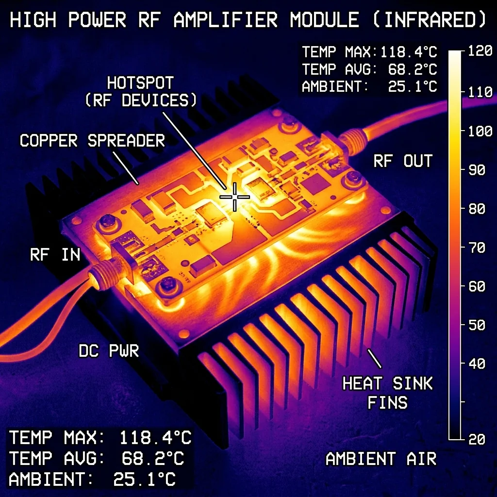
Heat Is the Silent Killer of RF Performance
In every RF system, electrical energy that does not reach the antenna is converted into heat. In a high-power radar transmitter operating at 1,000 Watts, even a modest 2 dB of insertion loss between the amplifier output and the antenna means that 370 Watts of thermal energy must be dissipated somewhere in the signal chain. That heat must be managed, or it will degrade component performance, shift operating frequencies, and ultimately cause catastrophic failure.
At RF Essentials, thermal management is not an afterthought. It is designed into every high-power termination, waveguide assembly, and dummy load we manufacture. The material selection, the body geometry, and the mounting interface are all engineered to move heat away from the RF signal path as efficiently as possible.
Where Heat Comes From in the RF Chain
Waveguide Terminations and Dummy Loads
A waveguide termination is specifically designed to convert RF energy into heat. The absorbing element inside the termination deliberately dissipates the incoming signal. In a low-power test environment, this generates negligible heat. But when testing a transmitter at full rated power, the termination must absorb hundreds or thousands of Watts continuously. The entire absorbed power becomes thermal energy that must be conducted through the termination body and rejected to the environment.
Power Amplifiers
Solid-state power amplifiers (SSPAs) at millimeter wave frequencies operate with efficiencies between 15% and 40%, depending on the semiconductor technology (GaN, GaAs, InP). A GaN amplifier delivering 100 Watts of RF output with 30% efficiency consumes 333 Watts of DC power. The remaining 233 Watts is dissipated as heat in the transistor junction. If the junction temperature exceeds the rated maximum (typically 200°C for GaN), the device fails.
Material Thermal Conductivity
The rate at which heat flows through a material is governed by its thermal conductivity. In waveguide component design, the body material is both the RF conductor (via the skin depth layer) and the primary thermal path.
| Material | Thermal Conductivity (W/m·K) | Electrical Conductivity (%IACS) | Typical Use |
|---|---|---|---|
| OFHC Copper (C10100) | 391 | 101% | High-power terminations, critical RF components |
| Aluminum 6061-T6 | 167 | 43% | Lightweight waveguide assemblies, heat sinks |
| Brass (C36000) | 115 | 26% | Standard waveguide flanges, structural bodies |
| Stainless Steel 304 | 16 | 2.4% | Avoid for thermal paths; mechanical fasteners only |
Engineering Insight: OFHC copper has 3.4x the thermal conductivity of brass. For high-power waveguide terminations, the difference between a copper body and a brass body can mean the difference between a component that operates reliably at 500 Watts and one that overheats and damages the absorbing element at 300 Watts.
Thermal Design of High-Power Terminations
RF Essentials high-power waveguide terminations use OFHC copper bodies for maximum thermal conductivity. The absorbing element (a precision-tapered lossy material) converts the RF energy to heat at the tip, where the waveguide cross-section is smallest. The heat flows radially outward through the copper body to the external mounting surface.
For power levels above 200 Watts, we incorporate cooling fins or a forced-air cooling interface. For power levels above 500 Watts, we offer liquid-cooled configurations where chilled water circulates through channels machined into the termination body. The water absorbs the heat and carries it to an external radiator, allowing continuous operation at power levels that would destroy a passively cooled component in minutes.
Derating Curves
Every high-power termination has a power derating curve that defines the maximum safe operating power as a function of ambient temperature. At 25°C ambient, a termination might be rated for 500 Watts CW. At 50°C ambient (common in outdoor equipment shelters), that same termination might derate to 350 Watts. At 85°C (military specification temperature), it might derate to 200 Watts. We publish full derating data for every high-power product because operating beyond the derated limit will shorten the absorber life and void the warranty.
Thermal Interface Management
The thermal path does not end at the component body. The interface between the component's mounting flange and the system chassis is often the weakest link in the thermal chain. An air gap of even 50 micrometers between two metal surfaces dramatically reduces thermal conductivity. We recommend thermal interface materials (TIMs), such as indium foil or thermal grease, at all high-power mounting interfaces. Proper bolt torque and flat mating surfaces are equally critical.
Conclusion
Thermal management is an engineering discipline that directly determines the power handling capability, reliability, and operational lifetime of every high-power RF component. Material selection, body geometry, cooling method, and interface management all contribute to the thermal resistance budget. At RF Essentials, we design thermal performance into every product from the initial concept, because a component that cannot manage its heat cannot meet its RF specification.
RF Essentials manufactures high-power waveguide terminations with OFHC copper bodies and optional liquid cooling for continuous high-power operation.
Frequently Asked Questions
Where does the heat come from in a high-power RF chain?
Any electrical energy that does not reach the antenna becomes heat. A termination deliberately converts absorbed RF into heat, so testing a 1,000 watt transmitter dumps that full power into the load. A GaN amplifier running at 30 percent efficiency to deliver 100 watts dissipates 233 watts in its junction and fails above roughly 200 C. Even 2 dB of insertion loss on a 1 kilowatt transmitter means 370 watts must be shed somewhere in the chain.
Why does body material matter so much for high-power waveguide components?
The component body is both the RF conductor, through the skin-depth layer, and the primary thermal path. OFHC copper conducts heat at 391 watts per meter-kelvin against about 115 for brass, roughly 3.4 times better. In practice that difference can mean a copper-body termination operating reliably at 500 watts where a brass one overheats and damages its absorber at 300 watts. Material choice sets the power ceiling as much as geometry does.
When does a high-power termination need liquid cooling?
Finned bodies and passive convection suffice up to a point, but above about 200 watts a high-power termination needs cooling fins or a forced-air interface, and above 500 watts a liquid-cooled configuration that circulates chilled water through channels in the body to an external radiator. Each part also carries a derating curve, so a 500 watt rating at 25 C may fall to 350 watts at 50 C and 200 watts at 85 C, and exceeding the derated limit shortens absorber life.