The Catastrophic Threat of Mismatched Impedance
During my time as a Senior Electrical Engineer at Raytheon Integrated Defense, working on massive phased array systems, there was one unwritten rule in the lab that you learned on your first day: Never power up a high-power amplifier without a termination. A multi-kilowatt GaN power amplifier (PA) module is a highly volatile piece of engineering. When it generates forward RF power, that energy must go somewhere. If the energy reaches the end of an open or shorted waveguide, the physics of electromagnetism dictates that it will bounce right back.
In radar engineering, we call this reflection. When hundreds of watts of reverse power travel back down the waveguide into the delicate output stage of a solid-state amplifier, the resulting voltage standing wave can instantaneously blow out the active die, vaporizing tens of thousands of dollars of hardware in milliseconds.
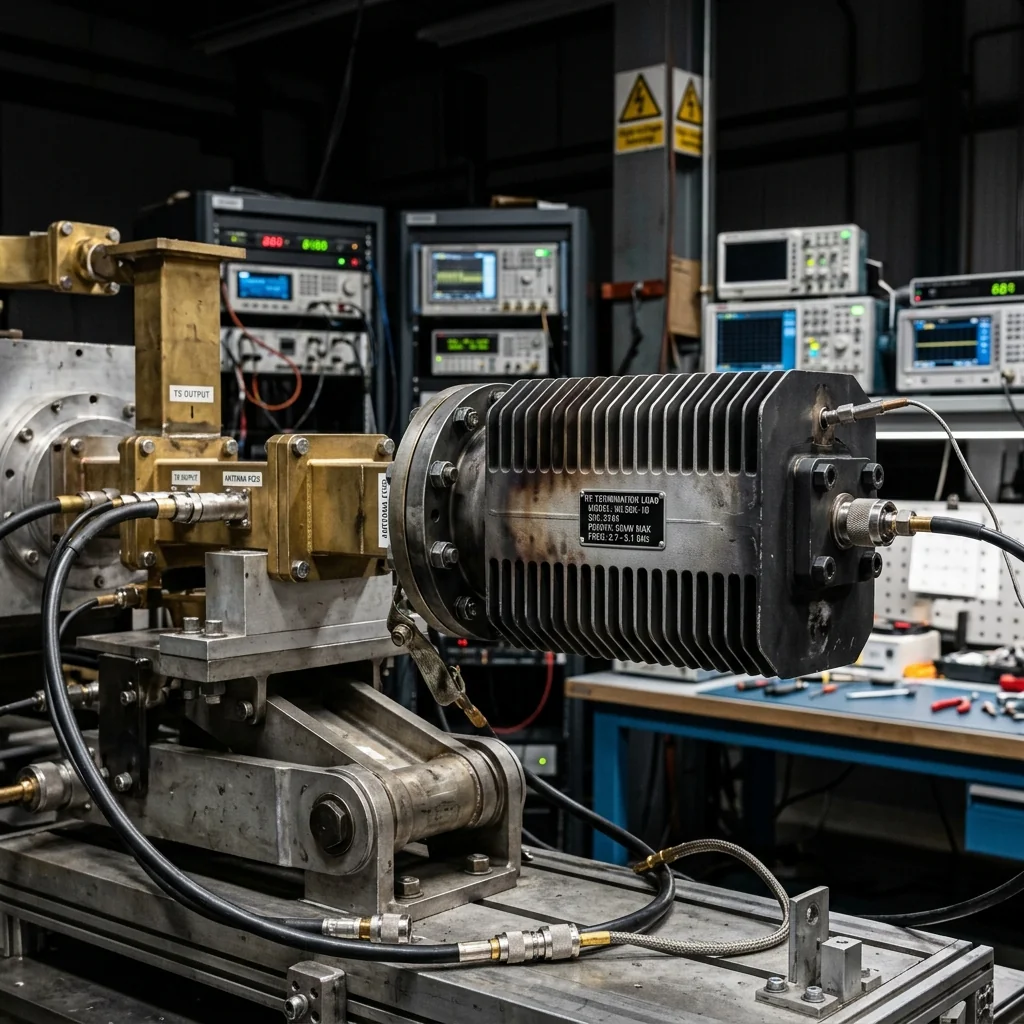
To safely test a radar transmitter on the bench, without actually radiating energy into the atmosphere, we bolt a high-power RF termination (often called a "dummy load") to the output flange. The termination acts as a thermodynamic sponge, absorbing 100% of the electromagnetic energy and converting it entirely into heat.
The Physics of the Perfect Match
Later in my career, as an Application Engineer at Rohde & Schwarz, I saw the other side of the equation. Test equipment like high-end Vector Network Analyzers (VNAs) depend entirely on mathematically perfect termination loads to establish their calibration planes. If your termination load isn't perfectly matched to the characteristic impedance of your waveguide (e.g., 50 ohms equivalent), it will reflect a microscopic portion of the signal, corrupting your S-parameter measurements.
VSWR = (1 + |Γ|) / (1 - |Γ|)
Where Γ is the Reflection Coefficient: Γ = (ZL - Z0) / (ZL + Z0)
A perfect termination has an impedance (ZL) exactly equal to the waveguide's characteristic impedance (Z0), resulting in a Reflection Coefficient of 0 and a perfect VSWR of 1.0:1. In reality, a high-quality waveguide termination achieves a VSWR of around 1.05:1 (Return Loss > 32 dB), meaning 99.7% of the power is safely absorbed.
Thermal Dissipation in High-Power Loads
When you are testing a continuous-wave (CW) or high-duty-cycle pulsed radar system, the amount of thermal energy dumped into the dummy load is extreme. The laws of thermodynamics cannot be cheated: if a transmitter is outputting 1,000 Watts of RF power, the termination must dissipate 1,000 Watts of thermal heat.
Inside the termination, the RF wave strikes a wedge-shaped piece of lossy material, typically carbon-loaded ceramic or silicon carbide. The wedge shape is critical; it creates a gradual, tapered impedance transition that prevents the wave from bouncing off the flat face of the material. As the wave penetrates the wedge, the electromagnetic field creates massive friction at the molecular level, generating heat.
This heat must be rapidly conducted away from the ceramic absorber. High-power terminations are constructed with massive, heavy-duty aluminum or copper housings heavily finned to maximize surface area. In the most extreme radar test applications, such as Aegis or Patriot arrays, the terminations feature liquid cooling channels where chilled ethylene-glycol actively wicks the heat away from the absorber block.
Classifying Termination Architectures
Not all terminations are built for the same task. As we built out our manufacturing capabilities at Precision mmw and now RF Essentials, we segment termination designs into specific power profiles tailored to the test environment.
| Termination Class | Power Handling | Cooling Method | Primary Application |
|---|---|---|---|
| Low Power (Precision) | 0.5W to 2W (CW) | Passive (No fins) | VNA Calibration, benchtop receiver testing, LNA isolation. |
| Medium Power | 10W to 50W (CW) | Convection (Finned body) | T/R module driver testing, local oscillator termination. |
| High Power | 100W to 2,000W+ (CW) | Forced Air / Liquid Cooled | Final PA stage testing, full transmitter array burn-in. |
The Slide Toward mmWave Radar
Historically, high-power defense radars operated primarily in the L, S, and X-bands. But modern battlefield architectures are pushing toward Ku, K, and Ka-bands (12 GHz to 40 GHz) for high-resolution targeting and missile seeker heads. As the frequency increases, the physical dimensions of the waveguide shrink dramatically.
A WR-28 waveguide (operating around 35 GHz) has an internal aperture of just 0.280 x 0.140 inches. Trying to dissipate 100 Watts of heat inside an aperture that small is an immense metallurgical challenge. The absorbing wedge must be machined to microscopic tolerances because even a 1-mil discrepancy in the taper can cause a spike in VSWR, reflecting power back into the Ka-band transmitter.
Conclusion
Dummy loads are rarely the most glamorous part of a radar system, but they are the unsung heroes of the test lab. Without precision RF terminations, it would be impossible to validate the high-power GaN amplifiers that power modern AESA architectures. Whether you are calibrating a Rohde & Schwarz VNA with a 1-Watt precision load, or doing a full-power burn-in on a transmitter array using a liquid-cooled block, the termination is the absolute endpoint of the signal chain. If it fails, everything upstream fails with it.
At RF Essentials, we bring decades of front-line engineering experience to manufacturing terminations that you can trust your hardware to. We know exactly what happens when a load fails, which is why we build ours not to.
RF Essentials manufactures precision waveguide terminations for radar testing, from low-power VNA calibration loads to liquid-cooled high-power dummy loads. All products are made in the USA.
Frequently Asked Questions
Why must you never power a high-power amplifier without a termination?
RF energy that reaches an open or shorted waveguide reflects straight back, and hundreds of watts of reverse power create a standing wave that can destroy the amplifier's output die in milliseconds, vaporizing tens of thousands of dollars of hardware. Bolting a high-power termination, or dummy load, to the output flange absorbs 100 percent of the energy and converts it to heat, so the transmitter can be tested on the bench safely without radiating into the air.
Why does termination VSWR matter for test and measurement?
A calibration load that is not perfectly matched reflects a small portion of the signal and corrupts S-parameter measurements, because a VNA establishes its calibration planes against that load. A perfect termination has a reflection coefficient of zero and a VSWR of 1.00 to 1, while a high-quality waveguide load reaches about 1.05 to 1, more than 32 dB of return loss, which means it safely absorbs 99.7 percent of the incident power.
How do high-power terminations dissipate the heat?
Thermodynamics cannot be cheated: a transmitter outputting 1,000 watts forces the load to shed 1,000 watts of heat. The wave strikes a wedge of carbon-loaded ceramic or silicon carbide whose gradual taper prevents reflection while molecular friction converts the field to heat. That heat is carried away by massive finned aluminum or copper housings, and in extreme Aegis or Patriot test loads by liquid-cooled glycol channels that actively wick it from the absorber block.