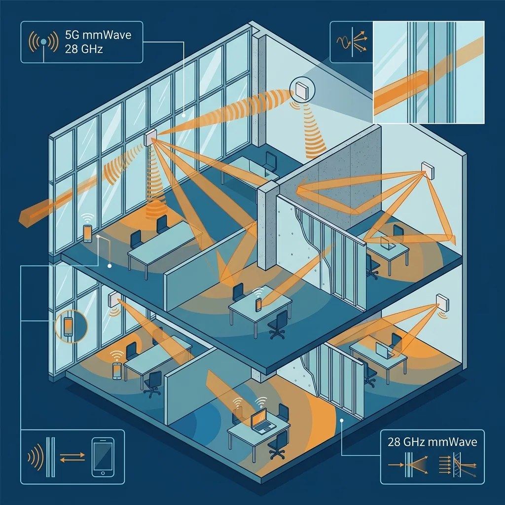
Millimeter wave 5G at 28 GHz delivers remarkable throughput in outdoor line-of-sight conditions, but the moment that signal encounters a building envelope, the physics change dramatically. A standard insulated glass unit (IGU) with low-emissivity coating attenuates 28 GHz signals by 25 to 40 dB. A brick wall adds another 25 to 35 dB of penetration loss. By comparison, the same materials attenuate sub-6 GHz signals by only 3 to 8 dB. This gap is the central engineering problem of mmWave 5G deployment: most mobile data consumption happens indoors, but the frequencies that deliver gigabit throughput are effectively blocked by the very structures where users need them most.
This article examines the measured penetration loss data for common building materials, the indoor propagation characteristics at 28 GHz, and the three primary architectural approaches for delivering indoor mmWave coverage.
1. Outdoor-to-Indoor Penetration Loss
Penetration loss at millimeter wave frequencies depends on the building material, its thickness, the angle of incidence, and, critically, the type of window glazing. Modern energy-efficient buildings are the worst case for mmWave penetration because low-E coatings contain metallic oxide layers that reflect RF energy in addition to infrared radiation.
| Material | Penetration Loss at 3.5 GHz | Penetration Loss at 28 GHz | Notes |
|---|---|---|---|
| Clear Glass (single pane) | 2-4 dB | 4-8 dB | Best case for OTI coverage |
| Low-E Coated IGU | 5-8 dB | 25-40 dB | Worst case; metallic oxide reflection |
| Tinted Glass (no Low-E) | 3-6 dB | 8-15 dB | Metal oxide tint adds moderate loss |
| Brick (4" single wythe) | 6-10 dB | 25-35 dB | Dense masonry is nearly opaque at mmWave |
| Concrete (6" reinforced) | 10-15 dB | 35-50+ dB | Effectively no penetration |
| Wood Frame + Drywall | 3-5 dB | 5-10 dB | Residential construction is relatively transparent |
| Metal Stud + Drywall | 5-8 dB | 15-25 dB | Metal studs create periodic scattering |
The Low-E Problem: Over 80% of new commercial construction in North America uses low-emissivity glazing for energy code compliance. This single design choice adds 20 to 35 dB of penetration loss compared to plain glass, effectively making outdoor-to-indoor mmWave coverage impossible without dedicated indoor infrastructure. The energy efficiency goals and the wireless coverage goals are working against each other.
2. Indoor Propagation at 28 GHz
Once inside a building, 28 GHz signals propagate through a combination of line-of-sight paths, first-order reflections from smooth surfaces (glass, drywall, whiteboards), and diffraction around corners and obstacles. The indoor path loss exponent at 28 GHz ranges from 1.7 in open-plan offices with line-of-sight conditions to 4.5 in corridors and partitioned spaces.
Reflections are more specular at mmWave frequencies than at sub-6 GHz because the wavelength (10.7 mm at 28 GHz) is much smaller than most indoor surfaces. This means that reflected paths behave more like optical reflections, producing predictable coverage from smooth walls and ceilings but poor coverage from rough or irregular surfaces. Standard drywall and glass partitions provide useful reflected energy; exposed concrete and textured acoustic panels do not.
Human body blockage is another significant factor. A human body standing in the signal path creates 20 to 35 dB of attenuation at 28 GHz. In dense indoor environments such as conference rooms, lobbies, and open-plan offices, body blockage from standing and moving occupants creates rapid, deep fading events that can drop the received signal below the demodulation threshold for high-order modulation schemes.
3. Indoor Coverage Architecture Options
Option A: Outdoor-to-Indoor (OTI) Through Windows
OTI coverage relies on outdoor base stations illuminating building interiors through windows. This approach works for buildings with clear or untinted glass, producing usable coverage within 5 to 10 meters of the window line. For buildings with low-E glazing, OTI coverage is not viable at 28 GHz without film removal or the installation of RF-transparent window sections, an approach that has been trialed by several operators in Asia.
Option B: Indoor Repeaters and CPE
A window-mounted Customer Premises Equipment (CPE) unit with an outdoor-facing antenna and an indoor-facing small cell provides a cost-effective solution for fixed locations. The CPE receives the outdoor mmWave signal on a directional antenna, demodulates and re-amplifies it, and retransmits into the building interior using either mmWave or sub-6 GHz on the indoor side. This approach avoids the building penetration loss entirely but requires per-location equipment installation.
Option C: Dedicated Indoor Small Cells
Purpose-built indoor mmWave small cells mounted on ceilings or walls provide the highest quality indoor coverage. These units connect to the operator core network through fiber or Ethernet backhaul and operate as independent access points. Ceiling-mounted units with 60-degree to 90-degree beamwidth antennas cover areas of 20 to 50 square meters per unit at 28 GHz, depending on the room geometry and furniture density.
The RF front-end module in an indoor small cell contains mmWave power amplifiers, beamforming antenna arrays (typically 8x8 or 16x16 patch elements), and the baseband processing that manages beam tracking for mobile users. The waveguide feed network connecting the PA stages to the antenna array must be designed for minimum insertion loss, because every 0.5 dB lost in the feed directly reduces the cell coverage radius by approximately 10%.
4. Link Budget for Indoor 28 GHz Coverage
A representative indoor link budget for a ceiling-mounted small cell operating at 28 GHz with 200 MHz channel bandwidth demonstrates the coverage constraints:
- Transmit power: 23 dBm (EIRP, after beamforming gain)
- Path loss at 10 m (free space): 71.4 dB
- Indoor excess loss (NLOS): 10-15 dB
- Body blockage margin: 10 dB
- Thermal noise floor (-174 dBm/Hz + 10log(200 MHz)): -91 dBm
- UE noise figure: 8 dB
- Required SNR for 64-QAM: 18 dB
- Receive sensitivity: -65 dBm
This leaves approximately 7 to 12 dB of link margin at 10 meters for NLOS conditions with body blockage. At 20 meters, the free-space path loss increases by 6 dB, consuming most of the margin and forcing the system to fall back to lower-order modulation (QPSK) with reduced throughput. These numbers explain why indoor mmWave coverage requires dense small cell deployment with 10 to 15 meter inter-site distances, far closer than the 200 to 500 meter spacing typical of outdoor macrocells.
5. Waveguide Components in Indoor mmWave Systems
Indoor mmWave infrastructure components use a mixture of waveguide and PCB-integrated transmission lines depending on the power level and frequency band. The antenna feed networks, calibration fixtures, and test systems for these products rely on precision WR-28 waveguide with the tight dimensional tolerances needed for consistent phase and amplitude balance across 64 or 256 antenna elements. RF Essentials supplies the passive waveguide components used in feed network prototyping, production calibration, and system-level testing.
RF Essentials manufactures precision WR-28 waveguide for 5G mmWave feed networks, calibration systems, and production test fixtures. Low insertion loss, precision flanges, and short lead times.
Frequently Asked Questions
Why is indoor 28 GHz coverage so difficult?
Building materials block millimeter wave far more than sub-6 GHz. A low-emissivity coated insulated glass unit attenuates 28 GHz by 25 to 40 dB, against just 5 to 8 dB at 3.5 GHz, and 6 inch reinforced concrete adds 35 to 50 dB or more. Since most mobile data is consumed indoors but the frequencies that deliver gigabit throughput are blocked by the building envelope, dedicated indoor infrastructure is usually unavoidable.
Why does energy-efficient glass make mmWave coverage worse?
Low-emissivity glazing contains metallic oxide layers that reflect RF energy as well as infrared, adding 20 to 35 dB of penetration loss compared with plain glass. Because over 80 percent of new North American commercial construction uses low-E glass to meet energy codes, outdoor-to-indoor coverage at 28 GHz becomes effectively impossible without indoor equipment. The energy efficiency goal and the wireless coverage goal end up working against each other.
How much does feed-network loss affect an indoor mmWave small cell?
The waveguide feed connecting the power amplifier stages to the antenna array must be designed for minimum insertion loss, because every 0.5 dB lost in the feed reduces the cell coverage radius by roughly 10 percent. With human body blockage adding 20 to 35 dB of fading and indoor non-line-of-sight path loss exponents reaching 4.5 in corridors, there is little budget to spare, so feed efficiency is a first-order design concern.