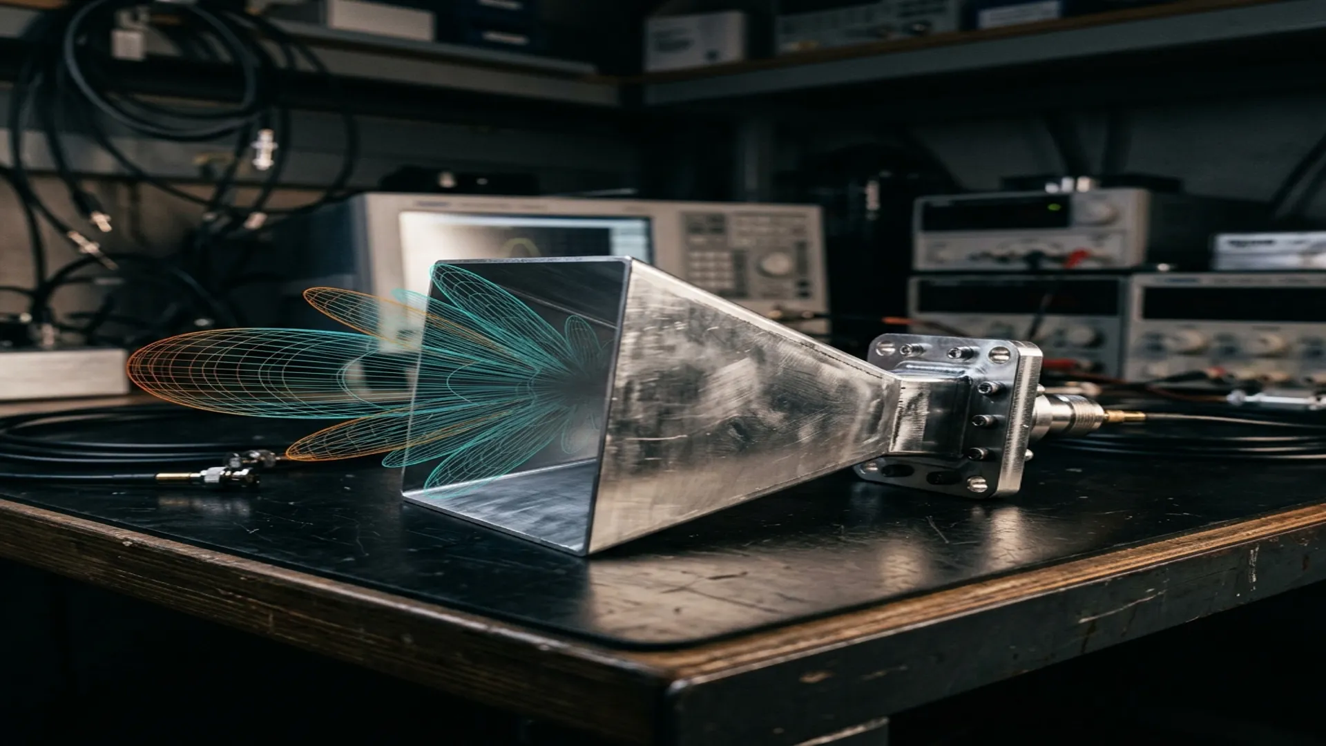
A waveguide horn antenna is a flared section of waveguide that transitions the guided electromagnetic mode into free-space radiation. It is the simplest, most predictable, and most widely used antenna in microwave and millimeter-wave engineering. If you have ever calibrated a network analyzer, characterized a radome, or set up a point-to-point link, you have almost certainly used a horn antenna as your reference.
This guide covers the four primary horn types, the physics that governs their gain and radiation patterns, the engineering tradeoffs in selecting one for a given application, and the critical waveguide flange interface details that determine whether your horn actually works with the rest of your system.
1. Why Horn Antennas Dominate Microwave Engineering
Horn antennas occupy a unique position in the RF engineer's toolkit. They are simultaneously a high-performance radiator and a calibration standard. Their dominance rests on three properties that no other antenna type combines as effectively:
- Predictable gain: The gain of a horn antenna can be calculated from its physical dimensions to within 0.1 dB using well-established analytical formulas. This makes horns the standard reference antenna for gain measurements. When you measure the gain of any other antenna, you are measuring it relative to a horn.
- Broadband impedance match: A properly designed horn presents a VSWR below 1.5:1 across the entire waveguide band. There is no matching network needed, no tuning required, and no narrow bandwidth penalty.
- Mechanical simplicity: A horn is a piece of precisely machined metal with no moving parts, no dielectric substrate, no feed network, and no active components. It does not degrade over time, does not require calibration (it is the calibration), and operates from cryogenic temperatures to +200°C without performance change.
2. Horn Types: Geometry, Trade-offs, and Applications
Pyramidal Horn
The pyramidal horn flares in both the E-plane and H-plane. It produces a pencil-shaped beam with controllable beamwidths in both planes. This is the most common general-purpose horn and the standard choice for gain calibration, antenna range illumination, and laboratory measurements.
The gain of an optimal-gain pyramidal horn is determined entirely by its aperture dimensions and wavelength:
Aphys = Physical aperture area (m²)
ηap = Aperture efficiency, typically 0.49 to 0.51 for an optimum pyramidal horn
For an optimal-gain design, the aperture efficiency converges to approximately 0.51 (51%). This means a pyramidal horn captures about half the power that would pass through an ideal aperture of the same size. The remaining 49% is lost to amplitude and phase taper across the aperture.
Conical Horn
A conical horn is the circular-waveguide equivalent of the pyramidal horn. It produces a symmetric beam (equal E-plane and H-plane patterns) and is the natural choice for circular-waveguide systems, satellite feeds, and applications requiring a rotationally symmetric pattern. Typical aperture efficiency is 0.52, slightly higher than pyramidal due to better phase uniformity in the circular cross-section.
Corrugated Horn
The corrugated horn has circumferential grooves (corrugations) cut into its inner walls. These corrugations force the field to satisfy a boundary condition that produces the hybrid HE11 mode, which has nearly identical E-plane and H-plane patterns, extremely low cross-polarization (below -30 dB), and low sidelobe levels (below -25 dB). Corrugated horns achieve aperture efficiencies of 0.70 to 0.80, significantly higher than smooth-wall designs.
Application Note: Corrugated horns are the standard feed for Cassegrain and Gregorian reflector antennas in satellite earth stations and radio telescopes. The low cross-polarization is critical for dual-polarization systems where polarization isolation of 30+ dB is required. The higher aperture efficiency directly translates to a smaller, lighter reflector for the same edge taper specification.
Sectoral Horn
A sectoral horn flares in only one plane (E-plane or H-plane) while remaining at waveguide width in the other. This produces a fan-shaped beam: narrow in the flared plane, wide in the unflared plane. Sectoral horns are used in applications requiring shaped coverage, such as airport surface detection radar, direction-finding arrays, and one-dimensional scanning systems.
| Horn Type | Aperture Efficiency | Cross-Pol | Beam Shape | Primary Application |
|---|---|---|---|---|
| Pyramidal | ~51% | -15 to -20 dB | Elliptical pencil | Calibration, gain standards, lab measurements |
| Conical | ~52% | -15 to -20 dB | Circular pencil | Satellite feeds, circular waveguide systems |
| Corrugated | 70-80% | < -30 dB | Symmetric pencil | Reflector feeds, radio telescopes, dual-pol systems |
| Sectoral (E/H) | ~40-50% | -10 to -15 dB | Fan beam | Shaped coverage, direction finding, 1D scanning |
3. Waveguide Bands and Flange Compatibility
A horn antenna is only as useful as its interface to the rest of your system. The waveguide flange is the mechanical and electrical connection point, and getting it wrong means reflections, mode conversion, and corrupted measurements.
| Waveguide | Frequency Range | Standard Flange | Typical Horn Gain (opt.) |
|---|---|---|---|
| WR-284 | 2.60 to 3.95 GHz | CPR-284G | 15 to 24 dBi |
| WR-137 | 5.85 to 8.20 GHz | CPR-137G | 15 to 24 dBi |
| WR-90 | 8.20 to 12.40 GHz | UG-39/U (Cover), UG-135/U (Choke) | 15 to 25 dBi |
| WR-42 | 18.0 to 26.5 GHz | UG-595/U (Cover), UG-596/U (Choke) | 15 to 25 dBi |
| WR-28 | 26.5 to 40.0 GHz | UG-599/U | 15 to 25 dBi |
| WR-15 | 50.0 to 75.0 GHz | UG-385/U | 20 to 25 dBi |
| WR-10 | 75.0 to 110.0 GHz | UG-387/U | 20 to 25 dBi |
Flange Rule: Always pair a cover flange with a choke flange. Cover-to-cover connections work but are sensitive to surface flatness and alignment. The choke flange provides a quarter-wave RF short that makes the connection tolerant of small gaps and misalignment, reducing the VSWR penalty from mechanical imperfection. For precision measurements, torque flange bolts to the manufacturer's specification and use alignment pins if provided.
4. Gain Calculation: The Practical Method
For a pyramidal horn with aperture dimensions a (H-plane width) and b (E-plane height), the maximum achievable gain at frequency f is:
Example: A WR-90 pyramidal horn with a 10 cm × 7 cm aperture at 10 GHz (λ = 0.03 m):
G = 10 · log₁₀ (4.5 × 0.10 × 0.07 / 0.03²) = 10 · log₁₀ (35.0) = 15.4 dBi
This matches the published gain for standard-gain WR-90 horns to within 0.3 dB, which is well within the measurement uncertainty of most antenna test ranges.
5. Radiation Pattern Characteristics
The radiation pattern of a horn antenna is determined by the field distribution across its aperture. For a smooth-wall pyramidal horn, the aperture field is approximately a cosine taper in the H-plane (due to the TE10 mode structure) and uniform in the E-plane. This produces the following pattern characteristics:
- H-plane pattern: Narrower beamwidth, lower sidelobes (first sidelobe typically -23 dB below peak). The cosine taper naturally suppresses sidelobes.
- E-plane pattern: Wider beamwidth, higher sidelobes (first sidelobe typically -13 dB below peak). The uniform aperture illumination produces higher sidelobes per Fourier transform theory.
- Half-power beamwidth (HPBW): Approximately HPBWE ≈ 53λ/b degrees and HPBWH ≈ 78λ/a degrees for an optimum pyramidal horn.
The E-plane/H-plane asymmetry is the primary limitation of pyramidal horns. When a symmetric pattern is required (for example, for illuminating a circular reflector with uniform edge taper), corrugated or dual-mode horns are used instead.
6. Common Design Mistakes
- Undersized flare length: If the horn is too short for its aperture, the phase error across the aperture exceeds the optimum value (approximately 0.375λ), and the gain drops below the theoretical maximum. The "optimum gain" condition requires a specific relationship between aperture size and flare length.
- Ignoring the phase center: The phase center of a horn is not at the aperture. It is located inside the horn, typically one-third to one-half of the slant length from the aperture. Using the aperture plane as the phase reference produces systematic errors in reflector feed placement and antenna range measurements.
- Neglecting diffraction at the aperture edges: At the edges of the horn aperture, diffracted fields create pattern ripple and affect the E-plane sidelobe structure. This effect is more pronounced at lower frequencies within the waveguide band.
- Flange gasket errors: Using a gasket or shim between waveguide flanges introduces a gap that can resonate and create narrowband VSWR spikes. If a gasket is required for weather sealing in outdoor installations, use an RF-transparent material and verify VSWR across the full band.
7. Selection Guide: Choosing the Right Horn
| Application | Recommended Horn Type | Key Selection Criteria |
|---|---|---|
| Gain calibration / reference | Pyramidal (standard gain) | Gain accuracy ±0.3 dB, traceable to national standards |
| Reflector antenna feed | Corrugated | Cross-pol < -30 dB, symmetric pattern, high ηap |
| Radar illuminator | Pyramidal or conical | Power handling, VSWR, gain uniformity across band |
| EMC testing | Pyramidal (broadband) | Known gain across wide frequency range for field strength calc |
| Direction finding | Sectoral (E or H) | Fan beam for azimuth or elevation-only scanning |
| Satellite earth station | Corrugated (Cassegrain feed) | Dual-pol isolation, low spillover, optimum edge taper |
RF Essentials manufactures precision waveguide horn antennas, flanges, adapters, and terminations across all standard waveguide bands from WR-284 through WR-10. All products are made in the USA with full dimensional inspection and test data.
Frequently Asked Questions
Why are horn antennas used as gain calibration standards?
A horn's gain can be calculated from its physical aperture and length to within about 0.1 dB using established formulas, and it holds a VSWR below 1.5 to 1 across the full waveguide band with no tuning. With no dielectric, no feed network, and no active parts, it does not drift over time or temperature. That predictability is why nearly every other antenna's gain is measured relative to a horn.
What aperture efficiency should I expect from different horn types?
An optimum pyramidal horn converges to about 51 percent aperture efficiency, and a conical horn is slightly higher near 52 percent, because roughly half the aperture power is lost to amplitude and phase taper. Corrugated horns reach 70 to 80 percent by supporting the HE11 mode, which is why they make smaller, lighter reflector feeds for the same edge taper and deliver cross-polarization below -30 dB.
Why should a cover flange always be paired with a choke flange?
The choke flange has a quarter-wave groove that forms an RF short at the joint, so current flows through the waveguide walls rather than across the metal-to-metal contact. Pairing a cover with a choke tolerates small gaps and slight misalignment with little VSWR penalty. Cover-to-cover joints work but are sensitive to flatness and alignment, and choke-to-choke pairings should never be used because the grooves interact unpredictably.