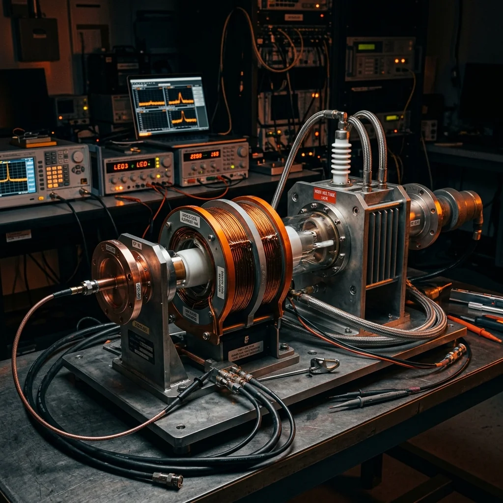
Electronic warfare demands a particular combination of RF performance that no other amplifier technology can deliver simultaneously: multi-octave bandwidth, kilowatt-class output power, and instantaneous frequency agility. The Traveling Wave Tube Amplifier (TWTA) has held this role for over sixty years because its vacuum electron beam interaction produces broadband amplification at power levels that semiconductor devices cannot match across equivalent bandwidth. While GaN solid-state technology has made significant inroads in narrowband EW applications, the TWTA remains the only production technology capable of generating 1 to 10 kW of continuous wave output across bandwidths spanning 2 to 18 GHz or wider.
This article covers the operating principles that give TWTAs their unique EW capabilities, the two primary tube architectures (helix and coupled-cavity), the waveguide output systems that handle the resulting power, and the practical engineering considerations for integrating TWTAs into operational EW platforms.
1. Why EW Needs Broadband Power
Electronic attack (EA) systems must transmit jamming signals across whatever frequency band the threat radar is operating on. Modern multifunction radars hop across wide frequency bands (often 6 to 18 GHz) on a pulse-to-pulse basis, requiring the jammer to follow with microsecond response times. A narrowband amplifier covering only a single radar band forces the system to carry multiple transmitter chains, each with its own TWTA, power supply, and high-power termination loads for dummy-load testing. A single broadband TWTA covering the full threat band reduces the transmitter to one chain, saving substantial weight, volume, and prime power on aircraft platforms where every kilogram matters.
2. Helix TWT Architecture
The helix TWT uses a precision-wound metal helix as the slow-wave structure. The helix's pitch is designed so that the electromagnetic wave traveling along the helix propagates at approximately the same velocity as the electron beam traveling through the center of the helix. This velocity synchronism allows continuous energy transfer from the beam to the RF wave over the length of the interaction region.
Helix TWTs achieve the broadest instantaneous bandwidth of any microwave amplifier, routinely covering 2:1 or 3:1 frequency ranges (e.g., 2 to 6 GHz, 6 to 18 GHz, or 2 to 18 GHz in wideband designs). Saturated power output for helix TWTs ranges from 10 watts for compact airborne electronic support measures (ESM) receivers to 2 kW for podded EA systems. The helix structure limits peak power handling because the thin helix wire can be damaged by arcing at very high RF field strengths, making helix TWTs better suited for CW or high-duty-cycle pulsed applications than for very high peak power radar transmitters.
3. Coupled-Cavity TWT Architecture
Coupled-cavity TWTs replace the helix with a series of resonant cavities coupled through slots or apertures. This structure handles much higher peak and average power levels than the helix because the cavity walls can dissipate heat more effectively and withstand higher RF field strengths without arcing. Coupled-cavity TWTs produce 1 to 100 kW peak power with 5 to 20 kW average power capability, making them the standard choice for high-power radar transmitters and standoff jamming platforms.
The trade-off is bandwidth. Coupled-cavity structures are inherently more narrowband than helix designs, typically covering 10% to 20% instantaneous bandwidth. For EW applications requiring both high power and broad bandwidth, system designers use banks of overlapping coupled-cavity TWTs or combine a wideband helix TWT driver with a high-power coupled-cavity final stage that covers a selected threat band.
4. Performance Comparison
| Parameter | Helix TWT | Coupled-Cavity TWT |
|---|---|---|
| Bandwidth | Multi-octave (2:1 to 10:1) | 10-20% of center frequency |
| CW Power | 10 W to 2 kW | 100 W to 20 kW |
| Peak Power | Up to 10 kW (limited) | 1 kW to 100+ kW |
| Gain | 40-60 dB | 30-50 dB |
| Efficiency (with MDC) | 30-50% | 35-55% |
| Typical EW Application | Self-protection jammer, DRFM exciter | Standoff jammer, radar transmitter |
| Weight (tube only) | 2-10 kg | 10-50 kg |
5. The Waveguide Output System
At power levels above 100 watts CW, the TWTA output must connect to the antenna through waveguide rather than coaxial cable. Waveguide handles the high power densities without the dielectric breakdown and thermal failure risks of coaxial connectors at these power levels. A typical TWTA EW transmitter output chain includes:
- Output waveguide section: Precision straight waveguide matched to the tube's output port flange (typically WR-137 for S-band, WR-90 for X-band, WR-62 for Ku-band).
- Directional coupler: A waveguide coupler sampling 20 to 30 dB of the output for power monitoring and automatic level control.
- Isolator or circulator: A ferrite device protecting the tube from reflected power caused by antenna VSWR excursions during aircraft maneuvering or antenna scan transitions.
- Waveguide switch: Routing the output between the operational antenna and a high-power termination load for ground testing and maintenance.
- Flexible waveguide section: Accommodating vibration and thermal expansion between the transmitter unit and the antenna pedestal.
Testing Matters: Every TWTA in an EW system must be tested at full rated power before installation. The test load must absorb the full CW output of the tube without exceeding a VSWR of 1.15:1 at the test frequency. A poor test load causes reflected power that can damage the tube's output window or collector, resulting in a tube replacement costing $50,000 to $200,000. RF Essentials manufactures high-power waveguide termination loads rated for these test conditions.
6. The GaN Challenge to TWTAs
GaN MMIC power amplifiers have begun to compete with helix TWTs in certain EW bands, particularly at X-band and Ku-band where GaN devices can produce 50 to 200 watts CW with 2 to 4 GHz instantaneous bandwidth. GaN-based solid-state transmitters offer several operational advantages: instant-on capability (no cathode warm-up time), graceful degradation (a failed transistor reduces output power by a fraction of a dB rather than killing the transmitter), and lower supply voltages that simplify the power conditioning.
However, no production GaN device or power-combined module matches the combination of bandwidth and power that a single helix TWT delivers across 2 to 18 GHz. The fundamental limit is the power combining network: as more transistor cells are combined to increase total output power, the combining losses, thermal management complexity, and physical size grow faster than the power output. For wideband EA systems requiring 500 watts or more across multi-octave bandwidths, the TWTA will remain the primary technology for the foreseeable future.
RF Essentials manufactures high-power waveguide terminations, straight sections, and bends for EW transmitter testing and integration. Rated for CW power levels matching operational TWTA output requirements.
Frequently Asked Questions
Why does electronic warfare still rely on traveling wave tube amplifiers?
Electronic warfare needs multi-octave bandwidth, kilowatt-class output power, and instant frequency agility all at once, a combination no other amplifier technology delivers together. A TWTA's vacuum electron-beam interaction produces broadband amplification at 1 to 10 kW of continuous wave output across 2 to 18 GHz or wider. GaN has taken narrowband bands, but across that full bandwidth at those power levels the TWTA remains the only production option.
What is the difference between helix and coupled-cavity TWTs?
The helix slow-wave structure gives the broadest bandwidth, covering 2 to 1 up to 10 to 1 ranges at 10 W to 2 kW, but its thin wire limits peak power because it can arc at high field strengths. Coupled-cavity tubes use resonant cavities that shed heat and tolerate higher fields, reaching 1 to 100 kW peak, but only 10 to 20 percent bandwidth. EW systems often pair a wideband helix driver with a high-power coupled-cavity final stage.
Why does a TWTA output use waveguide instead of coaxial cable?
Above about 100 watts of continuous wave power, coaxial connectors risk dielectric breakdown and thermal failure, so the tube output runs through waveguide. A typical chain includes a straight section matched to the tube flange, a directional coupler for automatic level control, an isolator or circulator protecting the tube from antenna VSWR excursions, a waveguide switch to route between the antenna and a high-power test load, and a flexible section for vibration.