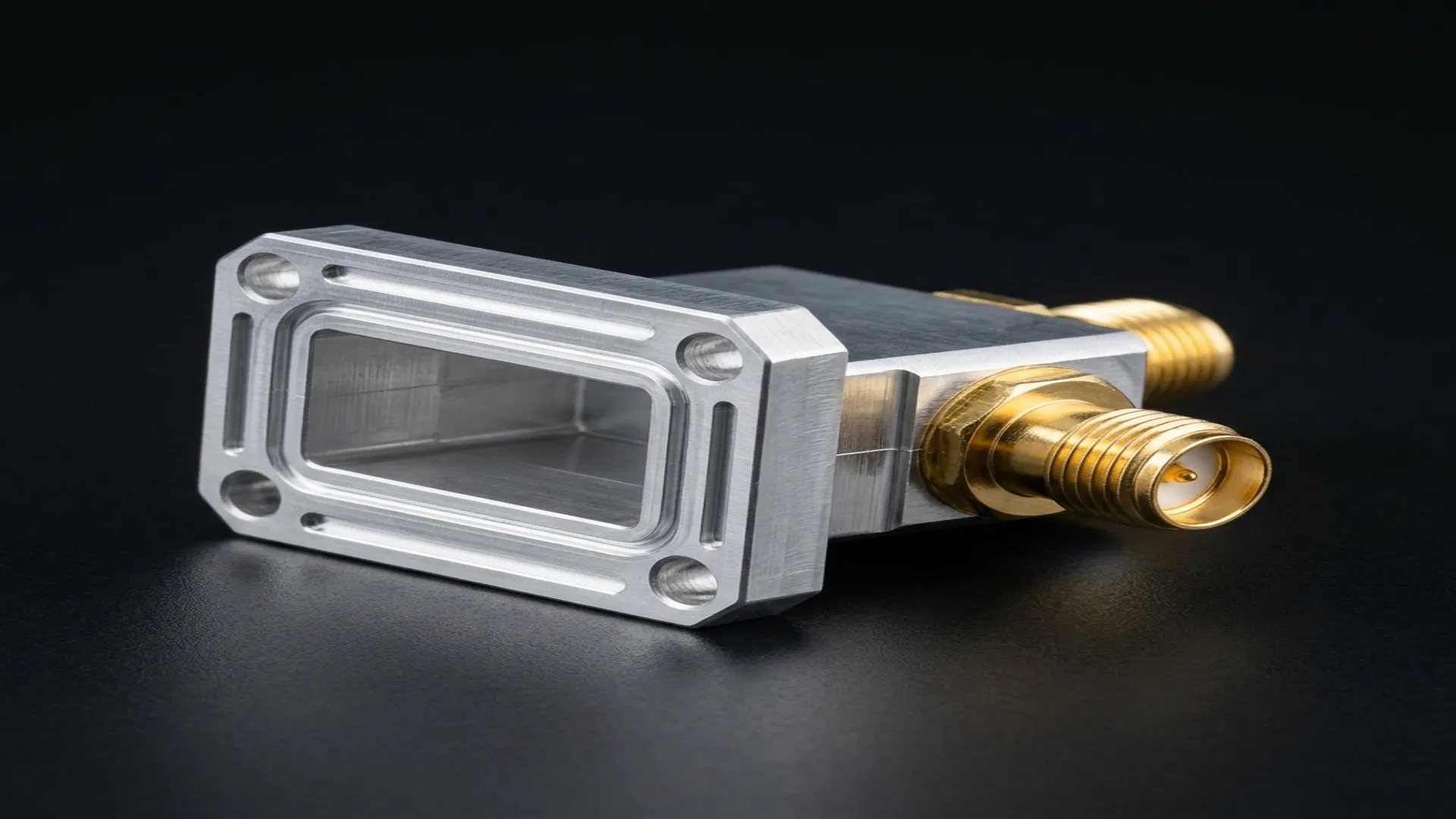
Every RF system that uses waveguide must eventually interface with coaxial cable. Test equipment has coaxial ports. Amplifiers have coaxial connectors. Mixers, filters, and switches are available in both coaxial and waveguide packages, but the interconnect between them requires a transition. The waveguide-to-coax transition (also called a waveguide adapter or waveguide-to-coax converter) is the component that converts the TE10 mode in a rectangular waveguide to the TEM mode in a coaxial transmission line.
This transition is one of the most critical components in a waveguide system because every dB of insertion loss and every mismatch ripple it introduces is multiplied by the number of transitions in the signal path. A typical test setup has four transitions (two on the DUT, two on the VNA cables). A poorly designed or damaged transition can render an entire measurement useless.
1. How It Works: Probe Coupling
The most common waveguide-to-coax transition uses a probe (also called a monopole or E-field probe) that extends from the center conductor of the coaxial connector into the waveguide cavity. The probe is positioned at a quarter-wavelength distance from the shorted back wall of the waveguide.
The Physics
- The coaxial center conductor extends through an aperture in the broad wall of the waveguide, forming a monopole antenna inside the waveguide.
- The probe couples to the electric field (E-field) of the TE10 mode, which is maximum at the center of the broad wall.
- The shorted back wall creates a standing wave that reinforces the coupling at the probe location (quarter-wave transformer effect).
- The probe depth, diameter, and distance from the back wall are tuned to achieve the best impedance match across the operating band.
2. Alternative: Loop Coupling
Loop-coupled transitions use a small wire loop that extends from the coaxial center conductor into the waveguide. The loop couples to the magnetic field (H-field) of the TE10 mode. Loop coupling is less common than probe coupling for standard transitions but is used in some specialized applications where the probe geometry is impractical (very small waveguide sizes, pressurized systems).
3. Loss Mechanisms
| Loss Source | Magnitude | Controllable? | Mitigation |
|---|---|---|---|
| Mismatch loss | 0.01 - 0.1 dB | Yes | Optimize probe geometry, tuning screws |
| Conductor loss (waveguide) | 0.01 - 0.05 dB | Partially | Silver plating, polished surfaces |
| Conductor loss (probe) | 0.01 - 0.03 dB | Partially | Gold or silver plated probe |
| Dielectric loss (bead) | 0.01 - 0.05 dB | Partially | Low-loss dielectric (PTFE, air-line) |
| Radiation loss | 0 - 0.02 dB | Yes | Proper flange seal, no air gaps |
| Total typical | 0.05 - 0.2 dB |
The Flange Connection Matters: A waveguide flange that is not flat, not clean, or not properly torqued can add 0.05 to 0.5 dB of loss per connection. At 40 GHz, a fingerprint on a flange face can measurably degrade the insertion loss. Always clean flange faces with isopropyl alcohol and lint-free wipes before assembly, and torque bolts to the specified value in a star pattern.
4. Selection Guide by Waveguide Band
| Waveguide | Frequency | Common Coax Connector | Typical Insertion Loss | VSWR |
|---|---|---|---|---|
| WR-284 | 2.6-3.95 GHz | N-Type | 0.05 dB | 1.10:1 |
| WR-137 | 5.85-8.2 GHz | N-Type or SMA | 0.08 dB | 1.15:1 |
| WR-90 | 8.2-12.4 GHz | SMA or N-Type | 0.10 dB | 1.15:1 |
| WR-62 | 12.4-18.0 GHz | SMA | 0.12 dB | 1.20:1 |
| WR-42 | 18.0-26.5 GHz | 2.92mm (K) | 0.15 dB | 1.25:1 |
| WR-28 | 26.5-40.0 GHz | 2.92mm (K) | 0.20 dB | 1.30:1 |
| WR-15 | 50.0-75.0 GHz | 1.85mm (V) | 0.30 dB | 1.35:1 |
| WR-10 | 75.0-110.0 GHz | 1.0mm (W) | 0.40 dB | 1.40:1 |
5. Specifying a Transition
When ordering a waveguide-to-coax transition, specify:
- Waveguide size: WR-XX designation (e.g., WR-90)
- Flange type: UG cover flange, UG choke flange, or CPR/CMR grooved flange
- Coaxial connector: SMA, N-Type, 2.92mm, 1.85mm, or 1.0mm
- Connector gender: Male or female (female SMA is most common for test applications)
- Connector orientation: End-launch or right-angle
- Performance spec: Maximum VSWR across the band, maximum insertion loss
- Power handling: CW and peak power rating
RF Essentials manufactures precision waveguide-to-coax transitions across all standard bands from WR-284 through WR-10. End-launch and right-angle configurations with SMA, N-Type, and 2.92mm connectors. Every adapter ships with measured S-parameter data.
Frequently Asked Questions
What does a waveguide-to-coax transition do?
It converts the TE10 mode traveling in a rectangular waveguide to the TEM mode in a coaxial line, so a waveguide system can interface with the coaxial ports on test equipment, amplifiers, and connectorized components. It is one of the most critical parts in a waveguide setup because every dB of its insertion loss and every mismatch ripple multiplies by the number of transitions in the path, and a typical test bench has four of them.
How does a probe-coupled waveguide-to-coax transition work?
The coaxial center conductor extends through an aperture in the waveguide broad wall as a monopole probe that couples to the electric field of the TE10 mode, which is strongest at the center of the broad wall. The probe sits about a quarter wavelength from the shorted back wall, whose standing wave reinforces the coupling like a quarter-wave transformer. Probe depth, diameter, and distance from the back wall are all tuned for the best match across the band.
Why does the flange connection matter so much for transition loss?
A waveguide flange that is not flat, not clean, or not properly torqued can add 0.05 to 0.5 dB of loss per connection, and at 40 GHz even a fingerprint on a flange face measurably degrades insertion loss. Always clean the mating faces with isopropyl alcohol and lint-free wipes and torque the bolts to the specified value in a star pattern, because the connection is often where a good transition quietly loses its performance.