Electronic warfare is the contest for control of the electromagnetic spectrum. It is fought with receivers that detect enemy emissions across multi-octave bandwidths in microseconds, transmitters that inject precisely crafted interference into those same bands, and protection systems that keep your own communications and radar functioning despite the enemy doing the same to you. Every EW system is, at its foundation, an RF system. The performance of the mission depends entirely on the performance of the hardware in the signal chain.
1. The Three Pillars of EW
| Pillar | Function | Key RF Subsystems |
|---|---|---|
| Electronic Support (ES) | Detect, intercept, identify, and locate enemy RF emissions | Wideband receivers, direction-finding antennas, signal classification |
| Electronic Attack (EA) | Deny, degrade, deceive, or destroy enemy use of the spectrum | High-power jammers, DRFM, expendable decoys |
| Electronic Protection (EP) | Protect friendly systems from enemy EA and unintentional interference | Frequency hopping, spread spectrum, adaptive nulling, hardened front ends |
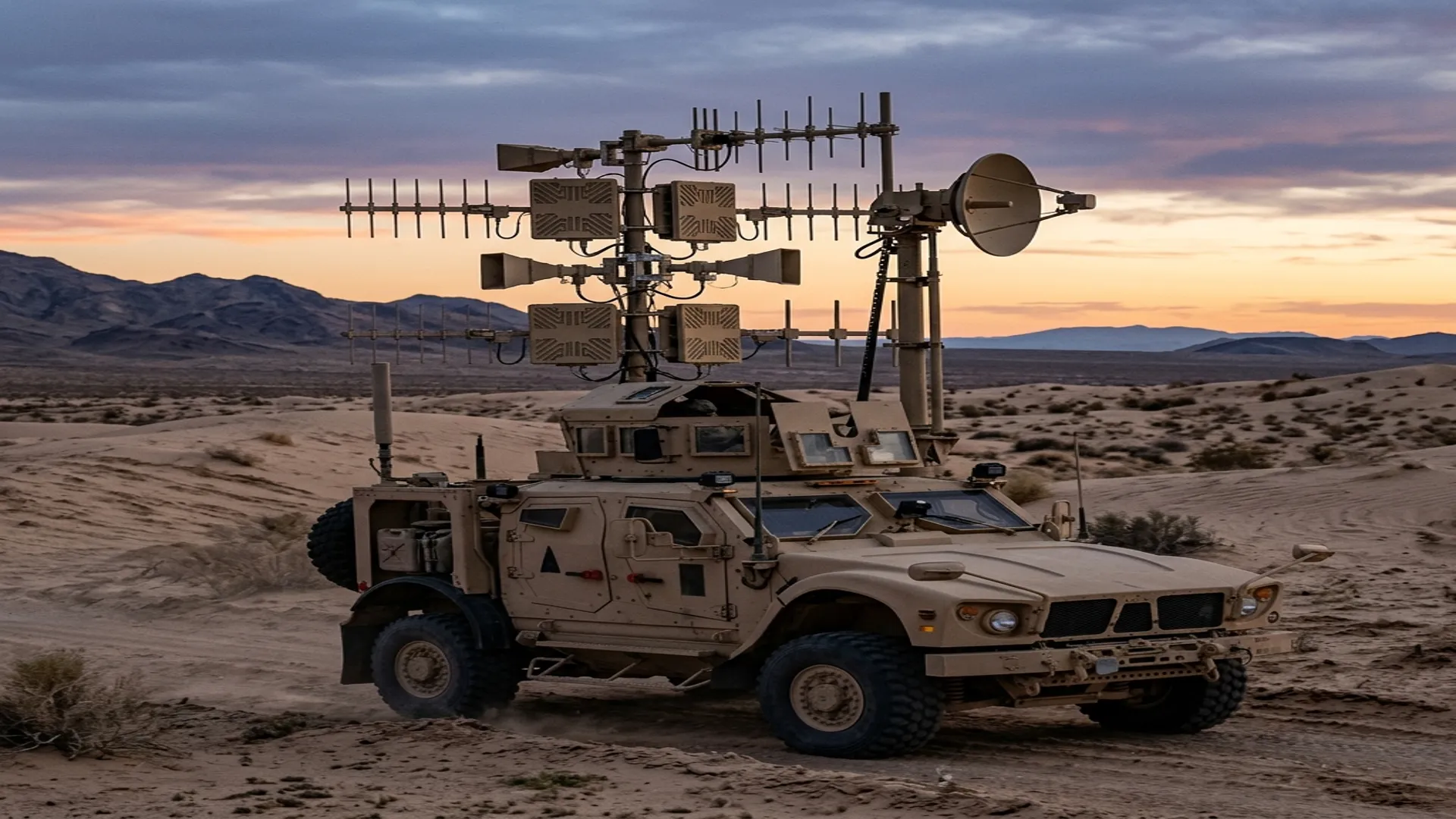
2. Electronic Support: The Wideband Receiver
An ES receiver must cover the entire threat band, typically 0.5 to 40 GHz, with enough sensitivity to detect low-power emitters at long range and enough dynamic range to handle nearby high-power radars without saturating. The fundamental architecture choices are:
Channelized Receiver
Splits the input band into narrow sub-bands using a bank of bandpass filters and detects energy in each sub-band simultaneously. Provides 100% probability of intercept (POI) across the full band. The filter bank is the most component-intensive element: a system covering 2 to 18 GHz with 20 MHz channel spacing requires 800 filters, each followed by a detector and video amplifier.
Digital Receiver (Wideband ADC)
Modern ES systems increasingly rely on direct digitization using high-speed ADCs (10+ GSPS, 12+ bits). A single ADC can digitize a 5 GHz instantaneous bandwidth, and the signal classification is performed in firmware on FPGAs. This approach reduces the analog filter bank complexity but demands extreme performance from the analog front end: the LNA, preselector filters, and frequency downconverters must maintain linearity across the full instantaneous bandwidth.
The Front End Matters Most: In an ES receiver, the wideband LNA and preselector determine the system's sensitivity, dynamic range, and survivability. A wideband LNA covering 2 to 18 GHz with 2 dB noise figure and +20 dBm IP3 is a challenging component to design and manufacture. The preselector filters must reject out-of-band energy (particularly nearby friendly transmitters) while passing the full threat band with minimal insertion loss.
3. Electronic Attack: Jamming Architecture
An EA system generates RF energy intended to interfere with enemy radar or communications. The two fundamental jamming architectures are:
Noise Jamming
Broadband noise energy spread across the target's operating bandwidth. Simple to implement (noise source + broadband amplifier + directional antenna) but power-inefficient. The jammer must generate enough power spectral density to exceed the target radar's processing gain. Effective against older radars but easily defeated by modern ECCM techniques.
Deception Jamming (DRFM)
A Digital RF Memory receives the enemy radar pulse, digitizes it, modifies it (adding false range, velocity, or angle information), and retransmits it. The enemy radar processes the false return as a real target. DRFM is far more effective than noise jamming because it exploits the radar's own signal processing against it.
DRFM hardware requires wideband ADCs (instantaneous bandwidth of 500 MHz to 2 GHz), high-speed memory, digital signal processing for waveform modification, and wideband DACs feeding a high-power transmitter chain. The latency from receive to retransmit must be less than 100 ns for range deception to be credible.
4. The RF Component Chain
Both ES and EA systems share common RF component requirements:
- Wideband antennas: Spiral antennas (2-18 GHz), sinuous antennas, or Vivaldi (tapered slot) antennas for multi-octave coverage with direction-finding capability.
- Wideband LNAs: GaAs or GaN MMIC amplifiers covering 2+ octaves with low noise figure and high linearity.
- High-power amplifiers: GaN solid-state PAs for EA transmitters. Power levels from 10W (self-protection) to 1 kW+ (stand-off jamming). Wideband operation (often 6-18 GHz) with graceful power rolloff at band edges.
- Switches and routing: High-isolation, fast-switching RF matrices for routing signals between multiple antennas and receiver/transmitter channels. PIN diode or GaAs MMIC switches with switching times under 10 ns.
- Waveguide components: Precision waveguide runs, couplers, and terminations in the high-power transmit chain. WR-90 and WR-62 components for X-band and Ku-band EA systems must handle peak powers of 1 kW+ with low VSWR.
5. The EW-Radar Convergence
Modern systems like the AN/APG-81 (F-35) and the Next Generation Jammer (NGJ) blur the line between radar and EW. The same AESA array that performs radar functions can also perform EA (jamming) and ES (passive intercept) by reprogramming the module-level phase shifters and T/R switch timing. This convergence means that the same TR modules, the same waveguide distribution networks, and the same thermal management systems must support both radar and EW modes without hardware changes.
RF Essentials manufactures precision waveguide components, high-power terminations, and integrated assemblies for EW and radar systems. ITAR-registered, made in the USA.
Frequently Asked Questions
What are the three pillars of electronic warfare?
Electronic Support detects, intercepts, identifies, and locates enemy emissions using wideband receivers and direction-finding antennas. Electronic Attack denies, degrades, or deceives the enemy's use of the spectrum with high-power jammers, Digital RF Memory, and expendable decoys. Electronic Protection keeps friendly systems working despite the enemy's attack through frequency hopping, spread spectrum, adaptive nulling, and hardened front ends. Every one of these is, at its foundation, an RF hardware problem.
What is the difference between noise jamming and DRFM deception jamming?
Noise jamming spreads broadband energy across the target's operating band. It is simple to build but power-inefficient and easily defeated by modern counter-countermeasures. Deception jamming using Digital RF Memory captures the enemy radar pulse, digitizes it, adds false range, velocity, or angle information, and retransmits it so the radar processes a false target. DRFM is far more effective because it turns the radar's own signal processing against it, demanding receive-to-retransmit latency under 100 ns.
Why does the receiver front end matter most in an electronic support system?
In an ES receiver the wideband LNA and preselector filters set the system's sensitivity, dynamic range, and survivability. A 2 to 18 GHz LNA with a 2 dB noise figure and a plus 20 dBm third-order intercept is genuinely hard to design and build, and the preselector must reject out-of-band energy, especially nearby friendly transmitters, while passing the full threat band with minimal loss. The front end ultimately determines how far and how reliably you can intercept a signal.