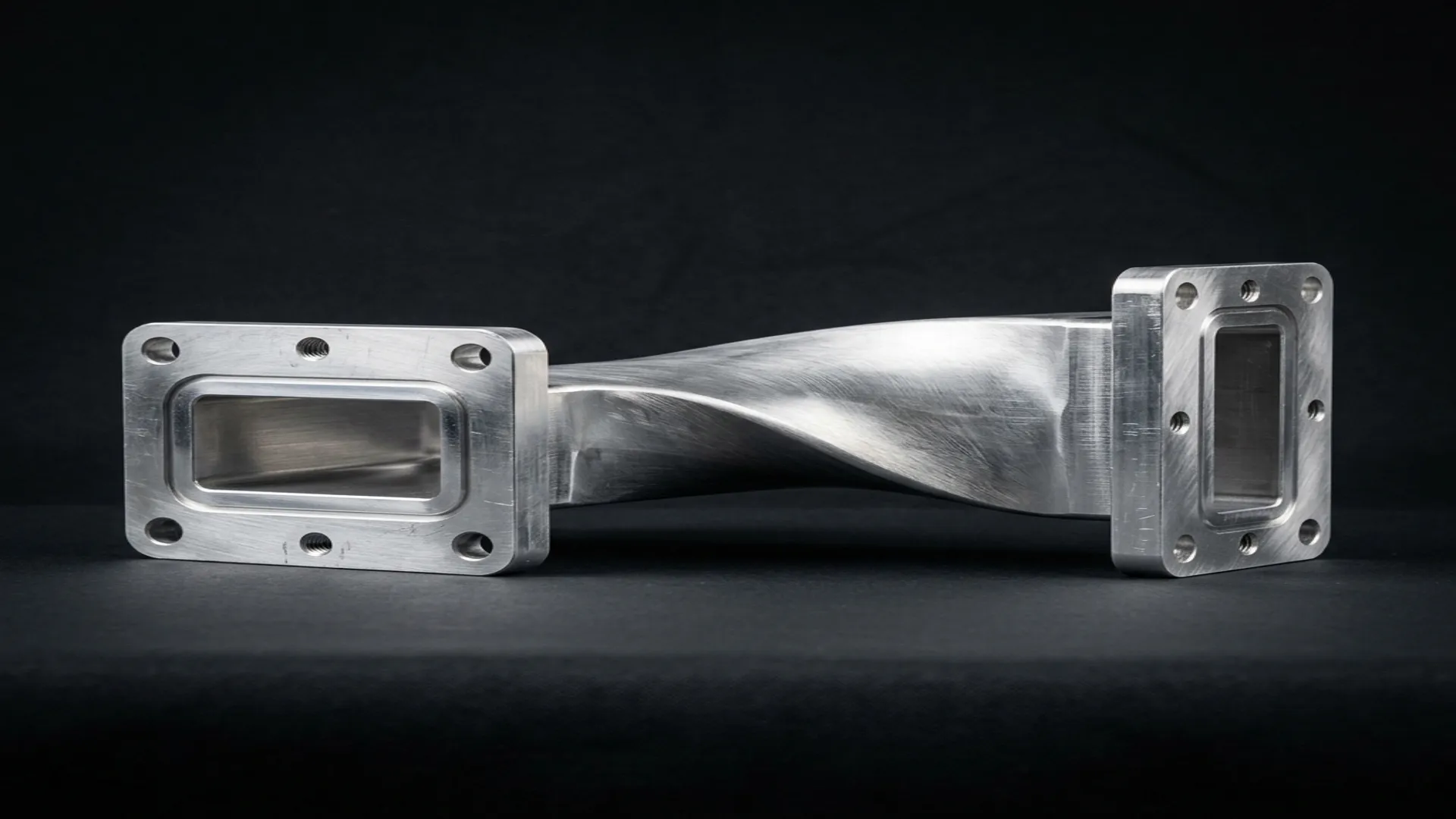
A waveguide twist rotates the polarization of the electromagnetic wave traveling through the waveguide by a specified angle. It is one of the simplest waveguide components in concept, one rectangular cross-section gradually rotating into another, but the engineering behind a low-loss, low-VSWR twist is more demanding than it appears. This article covers why twists are needed, how they work, the design variations, and the specifications that matter when selecting one.
1. Why Twists Exist
The dominant mode in rectangular waveguide (TE10) is polarized with the electric field parallel to the narrow wall (b dimension) of the waveguide. When two waveguide components need to be connected but their broad walls are not aligned (one is oriented horizontally, the other vertically), you need a twist to rotate the polarization by 90 degrees so that the TE10 mode in one section aligns with the TE10 mode in the other.
Common Scenarios
- Antenna feed alignment: A waveguide run from a transmitter exits horizontally, but the antenna feed requires vertical polarization. A 90° twist connects them.
- Equipment rack routing: Waveguide runs through equipment racks often require direction and orientation changes at each bulkhead. Twists accommodate these orientation mismatches.
- Dual-polarization systems: Satellite, radar, and communication systems that use both horizontal and vertical polarization require twists in the orthomode transducer (OMT) feed network.
- Test bench flexibility: Lab setups where components have different flange orientations. A 90° twist is a standard test bench accessory.
2. Twist Design Variations
| Type | Rotation | Length | VSWR | Best For |
|---|---|---|---|---|
| Gradual (continuous) | Smooth rotation over length | 1 to 3 guide wavelengths | 1.03:1 to 1.10:1 | Low-VSWR, broadband |
| Step twist | Discrete 45° steps | Shorter | 1.10:1 to 1.25:1 | Compact assemblies |
| 90° standard | Full quarter-turn | Varies by band | 1.05:1 typical | Polarization switching |
| 45° twist | Half quarter-turn | Shorter than 90° | 1.05:1 typical | Circular polarization feeds |
Gradual Twist
The gradual (continuous) twist smoothly rotates the waveguide cross-section from the input orientation to the output orientation over a length of one to three guide wavelengths. The gradual transition minimizes reflections because the cross-section changes slowly relative to the wavelength. This produces the lowest VSWR and insertion loss but requires the most physical length.
Step Twist
The step twist achieves the rotation using one or more discrete angular steps separated by short waveguide sections. A 90° step twist might use two 45° steps with a quarter-wave matching section between them. Step twists are more compact than gradual twists but have higher VSWR and narrower bandwidth.
Design Trade-off: Twist length vs. VSWR. A longer twist has lower VSWR because the impedance transition is more gradual. A WR-90 90° twist with a body length of 50 mm (approximately 1.5 guide wavelengths at 10 GHz) typically achieves VSWR below 1.05:1 across the full waveguide band. Shortening that to 25 mm degrades the VSWR to 1.10:1 or worse near the band edges.
3. Key Specifications
- Rotation angle: 90° is the most common. 45° twists are used in circular polarization feed networks. Custom angles are available for specific antenna geometries.
- VSWR: Specified across the full waveguide operating band. Premium twists achieve 1.03:1 to 1.05:1. Standard twists are typically 1.10:1 or better.
- Insertion loss: Typically 0.03 to 0.10 dB depending on material, plating, and length. Silver-plated twists have lower loss than unplated aluminum.
- Power handling: Determined by the minimum cross-section during the twist. The waveguide cross-section at the midpoint of a 90° twist is approximately square, which reduces the power handling compared to a straight section. Specify both CW and peak power ratings.
- Flange type: Input and output flanges (UG cover, UG choke, CPR, CMR). The input and output flanges are oriented 90° apart (for a 90° twist).
4. Manufacturing
Waveguide twists are manufactured by one of two methods:
- Machined from solid: CNC-machined from a solid aluminum billet. The internal twist profile is cut using specialized end mills or EDM (electrical discharge machining). Produces the most precise internal geometry and the best electrical performance. Higher cost.
- Formed/bent: A straight waveguide section is mechanically twisted using tooling. Works well for larger waveguide sizes (WR-137 and above) where the wall thickness is sufficient to withstand forming without cracking. Lower cost, but internal surface finish may be rougher, increasing insertion loss.
5. Installation Considerations
- Verify polarization before assembly: Mark the E-field orientation on both ends of the waveguide run before connecting the twist. A twist installed in the wrong direction rotates the polarization the wrong way, which is a surprisingly common field installation error.
- Do not over-torque flanges: The twist body is thinner than a straight section at the midpoint. Over-torquing the flange bolts can deform the waveguide cross-section, increasing VSWR.
- Support the twist body: In vertical runs, the twist should be supported independently of the flange connections to prevent mechanical stress on the waveguide joints.
RF Essentials manufactures precision waveguide twists in 45° and 90° configurations across all standard bands from WR-284 through WR-10. CNC-machined from solid aluminum with silver plating available. Every twist ships with measured VSWR data.
Frequently Asked Questions
Why would I need a waveguide twist?
The dominant TE10 mode is polarized with the electric field parallel to the narrow wall, so when two components must connect but their broad walls are not aligned, one horizontal and one vertical, a twist rotates the polarization, usually by 90 degrees, so the modes line up. Common cases include aligning a transmitter run to an antenna feed, routing through equipment racks, and feeding the orthomode transducer in a dual-polarization system.
What is the trade-off between a gradual twist and a step twist?
A gradual twist rotates the cross-section smoothly over one to three guide wavelengths, which keeps reflections low and achieves VSWR around 1.03 to 1.10 to 1, but it needs the most length. A step twist uses discrete 45 degree steps with short matching sections to stay compact, at the cost of higher VSWR and narrower bandwidth. Length buys match: a 50 mm WR-90 twist holds below 1.05 to 1, but halving it degrades the band edges to 1.10 to 1 or worse.
Does a waveguide twist reduce power handling?
Yes. The cross-section at the midpoint of a 90 degree twist is approximately square, which lowers power handling compared with a straight section, so specify both CW and peak ratings. The twist body is also thinner at the midpoint, so over-torquing the flange bolts can deform the cross-section and raise VSWR. In vertical runs, support the twist independently of the flanges to keep mechanical stress off the joints.