A directional coupler samples a known fraction of the RF power flowing through a transmission line, without significantly disturbing the main signal. It is the fundamental building block for power monitoring, VSWR measurement, signal leveling, and feedback loops in radar transmitters, satellite uplinks, and test systems. In waveguide systems, directional couplers achieve performance that coaxial couplers cannot match: higher directivity, lower insertion loss, and higher power handling, all in a single machined assembly with no solder joints or PCB traces to fail.
1. How a Directional Coupler Works
A directional coupler has four ports: Input, Output (also called Through or Mainline), Coupled, and Isolated. RF power entering the Input port splits: most of it exits the Output port (the mainline path), and a small, precisely controlled fraction exits the Coupled port. Ideally, no power exits the Isolated port.
The Key Parameters
| Parameter | Definition | Typical Range | Why It Matters |
|---|---|---|---|
| Coupling Factor | Power ratio: Input to Coupled port (dB) | 3 to 40 dB | Determines how much power is sampled |
| Directivity | Coupled - Isolated port level (dB) | 20 to 40+ dB | Ability to distinguish forward vs. reflected |
| Insertion Loss | Loss in mainline path (dB) | 0.05 to 0.5 dB | Impact on main signal |
| Isolation | Input to Isolated port (dB) | 40 to 70+ dB | Leakage to monitoring equipment |
| Main Line VSWR | Match of input/output ports | 1.05:1 to 1.20:1 | Reflection back to source |
Coupling Factor vs. Directivity: Coupling factor tells you how much power you sample. Directivity tells you how accurately you can distinguish forward power from reflected power. A coupler with 20 dB coupling and 35 dB directivity can measure forward power to within ±0.1 dB accuracy. The same coupler with only 15 dB directivity would have ±0.5 dB measurement uncertainty. For VSWR monitoring, directivity is the critical specification.
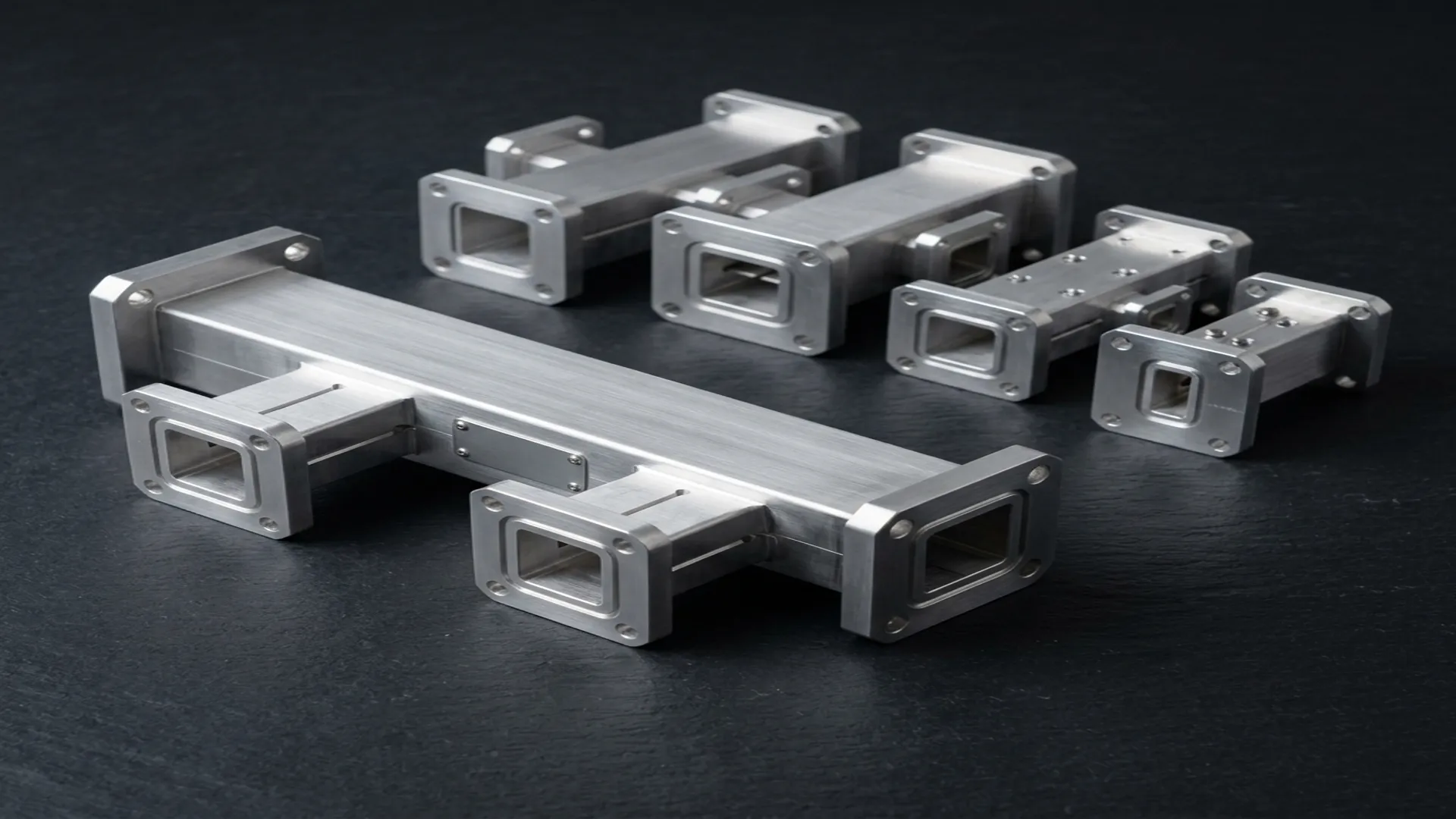
2. Waveguide Coupler Designs
Multi-Hole Coupler
Two parallel waveguides share a common broad wall with a row of small coupling holes. Each hole couples a small amount of energy between the waveguides. The holes are spaced so that the coupled signals add in phase in the forward direction and cancel in the reverse direction, creating the directional behavior. More holes and tighter spacing produce higher directivity and flatter coupling across the band.
Multi-hole couplers are the standard design for high-directivity applications. A well-designed multi-hole coupler can achieve 40+ dB directivity across the full waveguide band. Typical hole counts range from 5 (for moderate directivity) to 20+ (for instrument-grade directivity).
Cross-Guide Coupler
Two waveguides cross at a 90-degree angle with coupling apertures at the intersection. The cross-guide design is more compact than a multi-hole coupler and is commonly used for high coupling values (3 to 10 dB). Directivity is typically lower than multi-hole designs (20 to 30 dB).
Short-Slot Hybrid
A specialized 3 dB coupler where two parallel waveguides share a common narrow wall with a precisely machined slot. The short-slot hybrid splits the input power equally between the two output ports with a 90° phase difference. Used in balanced mixer feeds, duplexers, and monopulse radar comparators.
3. Choosing a Coupling Factor
| Coupling | Sampled Power | Application |
|---|---|---|
| 3 dB | 50% | Power splitting (hybrid), balanced mixers |
| 6 dB | 25% | High-sample power monitoring |
| 10 dB | 10% | Transmitter power monitoring, DPD feedback |
| 20 dB | 1% | High-power transmitter monitoring, radar |
| 30 dB | 0.1% | Very high power systems, minimal main-line impact |
| 40 dB | 0.01% | Megawatt radar, broadcast transmitters |
The rule: choose the highest coupling factor (most sampled power) that your measurement equipment can handle without overloading, while keeping the insertion loss in the mainline path acceptable for your system budget.
4. Dual-Directional Couplers
A dual-directional coupler integrates two couplers in one assembly: one sampling forward power, the other sampling reflected power. This allows simultaneous measurement of both forward and reflected power from which VSWR, return loss, and reflection coefficient can be calculated in real time.
Dual-directional couplers are standard equipment in radar transmitters (for fault detection), satellite earth stations (for uplink power control), and high-power broadcast systems (for antenna monitoring). The integrated design ensures that both the forward and reflected samples share the same coupling factor and phase reference, improving measurement accuracy.
5. Specifying a Waveguide Coupler
- Waveguide size: WR-XX designation
- Coupling factor: 10, 20, 30, or 40 dB (or custom)
- Coupling flatness: Variation of coupling factor across the band (e.g., ±0.5 dB)
- Directivity: Minimum across the operating band (e.g., 35 dB min)
- Mainline VSWR: Maximum across the band
- Coupled port VSWR: Maximum (matched or unmatched)
- Power handling: CW and peak, with any altitude/pressurization requirements
- Flange types: Mainline and coupled port flanges
- Isolated port termination: Internal matched load or external port
RF Essentials manufactures precision waveguide directional couplers in single and dual-directional configurations across all standard bands. Multi-hole designs with 35+ dB directivity. Coupling factors from 3 to 40 dB. Made in the USA with full test data.
Frequently Asked Questions
What is the difference between coupling factor and directivity?
Coupling factor is how much power the coupler samples, the ratio from the input to the coupled port. Directivity is how accurately it distinguishes forward power from reflected power, the difference between the coupled and isolated port levels. For VSWR monitoring, directivity is the critical spec: a 20 dB coupler with 35 dB directivity measures forward power to about plus or minus 0.1 dB, while only 15 dB directivity widens that to plus or minus 0.5 dB.
How do I choose a coupling factor for a directional coupler?
Pick the highest coupling factor, meaning the most sampled power, that your measurement equipment can handle without overloading, while keeping the mainline insertion loss within your system budget. As a guide, 10 dB suits transmitter power monitoring and DPD feedback, 20 to 30 dB suits high-power radar where main-line impact must stay small, and 40 dB is for megawatt radar and broadcast transmitters.
What is a dual-directional coupler used for?
A dual-directional coupler integrates two couplers in one body, one sampling forward power and one sampling reflected power, so VSWR, return loss, and reflection coefficient can be computed in real time. It is standard in radar transmitters for fault detection, in satellite earth stations for uplink power control, and in high-power broadcast systems for antenna monitoring. The integrated design keeps both samples on the same coupling factor and phase reference.