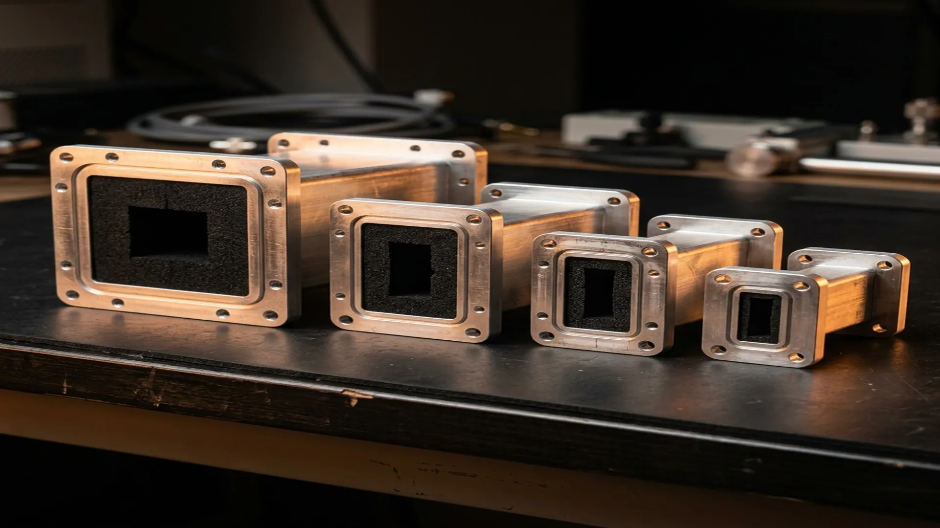
A waveguide termination is the simplest component in your RF system and one of the easiest to specify incorrectly. It is a matched load: a length of waveguide filled with an RF absorber material that converts incoming microwave energy into heat. No moving parts, no active circuitry, no tuning. And yet, selecting the wrong termination can damage your system, degrade your measurements, or void the warranty on your high-power amplifier.
This application note walks through the selection process from requirements to purchase order, covering the five specifications that matter and the common mistakes that waste time and money.
1. The Five Specifications That Matter
Every waveguide termination is defined by five parameters. Get all five right and the component disappears into your system without a second thought. Get any one wrong and you have a problem.
Waveguide Size and Frequency Band
The termination must match the waveguide size of your system. This seems obvious, but in practice, it is the most common source of ordering errors, particularly when systems use non-standard waveguide sizes or when the same frequency band can be served by multiple waveguide designations.
| Band | Waveguide | Frequency Range | Common Applications |
|---|---|---|---|
| S-band | WR-284 | 2.60-3.95 GHz | Marine radar, weather radar |
| C-band | WR-187 | 3.95-5.85 GHz | Satellite C-band, weather radar |
| X-band | WR-90 | 8.20-12.40 GHz | Military radar, satcom |
| Ku-band | WR-62 | 12.40-18.00 GHz | Satellite uplink/downlink |
| K-band | WR-42 | 18.00-26.50 GHz | 5G backhaul, automotive radar |
| Ka-band | WR-28 | 26.50-40.00 GHz | Satcom, 5G, AESA radar |
| V-band | WR-15 | 50.00-75.00 GHz | 60 GHz wireless, research |
| W-band | WR-10 | 75.00-110.00 GHz | Automotive radar, imaging |
VSWR (Impedance Match)
The VSWR specification tells you how well the termination absorbs incoming energy versus reflecting it. A perfect termination has a VSWR of 1.00:1, meaning zero reflection. In practice:
- 1.05:1 or better: Calibration-grade. Required for VNA calibration loads and precision measurement setups.
- 1.10:1 to 1.15:1: Standard lab-grade. Suitable for most test and measurement applications.
- 1.20:1 to 1.30:1: System-grade. Acceptable for in-system dummy loads, receiver protection, and general-purpose matched loads.
VSWR vs. Frequency: VSWR is not constant across the operating band. Most terminations achieve their best match at mid-band and degrade toward the band edges. Always verify the VSWR specification across the full frequency range you intend to use, not just at a single frequency. Datasheet VSWR is typically a worst-case value across the rated band.
Power Handling
Power handling is specified as average (CW) power and peak power. Average power determines the thermal load: the termination must dissipate this power as heat without exceeding its maximum operating temperature. Peak power determines the instantaneous electric field stress: if the peak field exceeds the breakdown threshold of the absorber material or the air gap, arcing occurs.
| Waveguide | Typical CW Power (Standard) | Typical CW Power (High-Power) | Typical Peak Power |
|---|---|---|---|
| WR-284 | 500 W | 2 kW | 100 kW |
| WR-90 | 200 W | 1 kW | 30 kW |
| WR-42 | 50 W | 200 W | 5 kW |
| WR-28 | 20 W | 100 W | 2 kW |
| WR-10 | 5 W | 20 W | 500 W |
Thermal Derating
Datasheet power ratings are specified at 25°C ambient temperature with adequate heat sinking. In real installations, ambient temperatures are higher and air flow may be restricted. Derate by 2.5% per degree Celsius above 25°C. A termination rated for 100W CW at 25°C is only rated for 62.5W at 40°C without forced-air cooling.
Flange Type
The termination flange must mate with your system. This means matching the flange standard (UG, CPR, CMR, or cover), bolt pattern, and alignment pin configuration. Using a cover flange termination with a choke flange system (or vice versa) changes the flange joint VSWR and can degrade the overall match.
2. Absorber Materials
The absorber inside a waveguide termination determines its frequency response, power handling, and temperature performance. Three material families dominate:
- Carbon-loaded epoxy/resin: The most common absorber for standard-power terminations. Good broadband match, moderate temperature tolerance (up to 150°C continuous). Cost-effective for general-purpose applications.
- Ferrite-loaded composites: Higher power handling than carbon-loaded materials. Better suited for high-power CW applications where sustained thermal loading is the primary concern.
- Precision-tapered absorbers: A wedge or pyramid-shaped absorber that provides a gradual impedance transition from air to full absorption. Achieves the lowest VSWR (1.03:1 or better) but is more expensive and fragile. Used in calibration-grade terminations.
3. Common Selection Mistakes
- Specifying average power only: A pulsed radar with 10W average power and a 1% duty cycle has a peak power of 1 kW. The termination must handle both.
- Ignoring altitude: At high altitude, reduced air pressure lowers the peak power handling due to decreased breakdown voltage. Derate peak power by 50% at 70,000 feet.
- Wrong flange orientation: Cover flanges and choke flanges must be paired correctly. Two cover flanges mated together will have higher VSWR than a cover-to-choke pair.
- Forgetting the heat sink: A termination converting 100W of RF to heat without a heat sink will exceed temperature limits within minutes. Always mount high-power terminations to a thermal mass or use forced-air cooling.
RF Essentials manufactures precision waveguide terminations from WR-284 through WR-10 in standard, high-power, and calibration-grade configurations. All products are made in the USA with full dimensional inspection and VSWR test data.
Frequently Asked Questions
What five specifications define a waveguide termination?
Five parameters fully specify a matched load: the waveguide size and frequency band, the VSWR or impedance match, the power handling stated as both average and peak, the thermal derating for ambient temperature, and the flange type. Get all five right and the termination disappears into the system. Get any one wrong, particularly power or flange, and you risk damage, degraded measurements, or a part that will not even mate.
Why do I need to specify both average and peak power for a termination?
Average power sets the thermal load the absorber must dissipate as heat, while peak power sets the instantaneous field stress that causes arcing if it exceeds the breakdown threshold. A pulsed radar at 10 W average and 1 percent duty cycle actually presents 1 kW peak, so a termination chosen on average power alone could arc and fail. Always rate a part against both numbers.
What VSWR grade should I choose for a waveguide termination?
Calibration-grade loads reach 1.05 to 1 or better and are needed for VNA calibration and precision measurement. Standard lab-grade falls around 1.10 to 1.15 to 1, and system-grade loads at 1.20 to 1.30 to 1 are fine for in-system dummy loads and receiver protection. VSWR is worst near the band edges, so verify the specification across your full frequency range, not at a single point.