Moisture inside a waveguide is the silent killer of RF performance. A single droplet of water in a WR-28 waveguide at Ka-band can increase insertion loss by several dB, shift the phase response, and in high-power systems, trigger arcing that permanently damages the waveguide interior. Pressurizing the waveguide with dry nitrogen or dehydrated air prevents this by maintaining a positive internal pressure that keeps moisture out and provides a controlled dielectric environment.
This application note covers the complete installation and pressurization procedure for waveguide assemblies, from unpacking to final leak test. It is written for field technicians and RF engineers installing ground station feed systems, radar waveguide runs, and outdoor antenna assemblies.
1. Pre-Installation Inspection
Before installing any waveguide component, perform these checks:
- Visual inspection of the waveguide interior: Look through each section with a bright light. The inside surface should be smooth, clean, and free of machining debris, fingerprints, or corrosion. Any surface contamination at Ka-band and above will increase insertion loss.
- Flange face inspection: The mating surfaces must be flat, clean, and free of nicks or scratches. Even a 0.001" burr on a WR-28 flange face can degrade the VSWR of the joint.
- O-ring inspection: For pressurizable flanges, verify that the O-ring is the correct size, material (typically Viton or silicone), and is free of cuts, flat spots, or contamination. Lightly coat the O-ring with a silicone-based vacuum grease before installation.
- Alignment pin verification: Confirm that all alignment pins are present, straight, and the correct diameter. Missing or bent pins will cause waveguide aperture misalignment.
2. Assembly and Torque Procedure
Proper bolt torque is critical for both RF performance and pressure integrity. Under-torqued joints leak. Over-torqued joints warp the flange face, distort the waveguide aperture, and can crack the flange body at higher frequencies where the flange material is thinner.
| Waveguide | Typical Bolt Size | Recommended Torque | Notes |
|---|---|---|---|
| WR-284 to WR-137 | #10-32 or 1/4-28 | 15 to 25 in-lbs | Larger flanges tolerate more torque |
| WR-112 to WR-62 | #6-32 or #8-32 | 8 to 15 in-lbs | Use a calibrated torque wrench |
| WR-42 to WR-28 | #4-40 | 4 to 8 in-lbs | Thin flanges; do not over-torque |
| WR-22 to WR-10 | #2-56 | 2 to 4 in-lbs | Precision torque required; damage risk is high |
Torque Sequence: Always tighten bolts in a cross pattern (star pattern), not sequentially around the bolt circle. Tighten to 50% of final torque on the first pass, then 100% on the second pass. This ensures even compression of the O-ring and uniform flange contact across the entire mating surface.
3. Pressurization Procedure
Gas Selection
- Dry nitrogen (N₂): The standard choice. Inert, dry (dew point below -40°C), inexpensive, and readily available from welding supply sources. Use industrial grade or better.
- Dehydrated air: An alternative where nitrogen is not available. Must be processed through a membrane or desiccant dryer to achieve a dew point below -40°C.
- SF₆ (sulfur hexafluoride): Used only in high-power applications where the waveguide must handle peak power levels exceeding the breakdown voltage of nitrogen. SF₆ has approximately 2.5 times the dielectric strength of nitrogen. Environmental regulations restrict its use in many jurisdictions.
Pressurization Steps
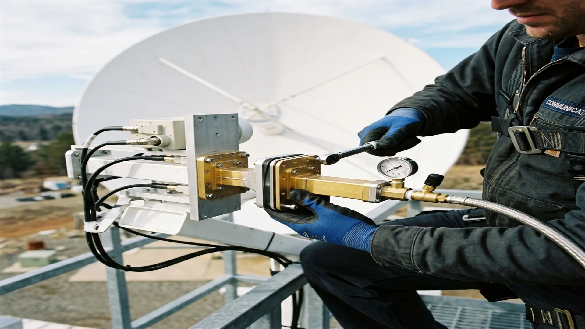
- Connect the nitrogen supply to the waveguide pressurization port through a regulator and a pressure gauge.
- Slowly pressurize to 0.5 PSI above ambient. Do not pressurize rapidly; sudden pressure changes can dislodge O-rings or pop alignment pins.
- Hold at 0.5 PSI for 15 minutes and monitor the pressure gauge. Any detectable pressure drop indicates a leak.
- If no leaks, increase to the operating pressure (typically 1 to 3 PSI above ambient for ground installations, 3 to 5 PSI for shipboard or harsh environments).
- Hold at operating pressure for 1 hour. Acceptable leak rate is less than 0.1 PSI/hour for most specifications.
4. Leak Detection and Troubleshooting
If the pressure test fails, locate the leak using one of these methods:
- Soap bubble test: Apply a soapy water solution (or commercial leak detection fluid) to each flange joint while the system is pressurized. Bubbles indicate the leak location. This is the fastest and most practical field method.
- Helium mass spectrometer: For systems with very tight leak specifications (hermetic seals, space-qualified hardware), helium leak testing is the standard. Pressurize with helium and use a sniffer probe at each joint.
The most common leak sources, in order of frequency:
- Damaged or missing O-rings (50% of field leaks)
- Under-torqued bolts (25%)
- Scratched or nicked flange faces (15%)
- Cracked or porous pressure windows (10%)
5. Common Installation Errors
- Installing waveguide without removing shipping caps: Shipping caps protect the flange faces and waveguide interior during transit. Remove them. They are not part of the assembly.
- Using pipe thread sealant on pressurization fittings: PTFE tape or pipe dope can shed particles into the waveguide interior. Use metal-to-metal fittings with proper O-ring seals.
- Exceeding bend radius limits: Flexible waveguide sections have a minimum bend radius. Exceeding it kinks the waveguide, permanently increasing VSWR and insertion loss.
- Skipping the dry purge: Before pressurizing, purge the entire waveguide system with dry nitrogen at low flow rate for 10 to 15 minutes to flush out any moisture that entered during installation. Then seal and pressurize.
RF Essentials manufactures pressurizable waveguide assemblies with CPR-style flanges, integrated O-ring grooves, and pressure test certification. Available in all standard waveguide sizes from WR-284 through WR-10.
Frequently Asked Questions
Why are waveguide assemblies pressurized with dry nitrogen?
Moisture is the silent killer of waveguide performance. A single droplet in a WR-28 line at Ka-band can add several dB of insertion loss, shift the phase, and trigger arcing that permanently damages the interior in high-power systems. Pressurizing with dry nitrogen, typically 1 to 3 PSI above ambient, keeps moisture out and maintains a controlled dielectric environment. Nitrogen is inert, dry to below -40 C dew point, and inexpensive.
How should waveguide flange bolts be torqued?
Use a calibrated torque wrench and tighten in a cross or star pattern, 50 percent on the first pass and 100 percent on the second, so the O-ring compresses evenly. Torque scales with flange size, from 15 to 25 inch-pounds on WR-284 down to just 2 to 4 inch-pounds on WR-10. Over-torquing thin high-frequency flanges warps the face, distorts the aperture, and can crack the body.
What are the most common sources of pressurization leaks?
In field installations, damaged or missing O-rings cause about half of all leaks, under-torqued bolts about a quarter, scratched or nicked flange faces about 15 percent, and cracked or porous pressure windows the remaining 10 percent. A soap bubble test on each joint under pressure is the fastest way to locate one; helium mass spectrometry is reserved for hermetic or space-qualified hardware with very tight leak specifications.